Real-Time Sequencer Overview and Coordination for JCMT Subsystem Integration
The Real-Time Sequencer (RTS) provides essential coordination at the sub-millisecond level among standard telescope subsystems, enhancing programmability for non-standard components within the JCMT command structure (DRAMA). Recent developments include the delivery of a prototype to DRAO, completed CPLD design, fixed integration options, and initial signal configuration files. Although features such as time-stamping and full programmability are in progress, current capabilities assist in managing the data-taking cycle effectively and organizing physical connections for efficient operation.

Real-Time Sequencer Overview and Coordination for JCMT Subsystem Integration
E N D
Presentation Transcript
The Real-Time Sequencer B.D.Kelly, X.Gao
Provide coordination between standard telescope/instrument subsystems at the sub-mSec level. Provide programmability for coordinating non-standard subsystems. Interface with the overall JCMT command structure (DRAMA) Provide time-stamping of the data-taking cycle. Specification
Prototype has been delivered to DRAO. Supports standard subsystems. Final version of cpld design done. Choice of fixed integration or fixed sampling implemented. Time-stamping not yet implemented. Programmability not yet commissioned. Current Status
RTS Overview Observation driver ACSIS Four-signal real-time link Drama messages Drama messages HARP-B RTS Tel Configuration files
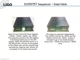
1 2 3 4 5 6 7 8 RTS Signal Sockets Output 1 Output 2 Input 1 Input 2 16 connection sockets
RTS Initialisation File <Connections> <System name=“TCS” socket=“1” /> <System name=“HARPB” socket=“2” /> <System name=“ACSIS” socket=“3” /> <System name=“SCUBA” socket=“4” /> <System name=“ROVER” socket=“5” /> <System name=“RXB3” socket=“6” /> </Connections> This provides a list of the physical connections. It doesn’t say whether these are standard or non-standard subsystems, and doesn’t say whether they will actually be used.
RTS Configuration File <Configuration> <TCS SC=“1” SR=“1” DV=“2” /> <HARPB SC=“1” SR=“1” DV=“2” /> <ACSIS SC=“1” SR=“1” DV=“2” /> </Configuration> The Configuration lists all the standard subsystems which are going to be involved in the subsequent sequence.
RTS Sequence File The most trivial sequence file is:- <Sequence/> This means that only the standard subsystems as listed in the Configuration file are going to be used.
RTS Sequence File (Cont.) <Sequence size=“4”> <position num=“1”> <putSC name=“RXB3” output=“1” value=“1”/> </position> <position num=“2”> <putSC name=“RXB3” output=“1” value=“1”/> </position> <position num=“3”> <putSC name=“RXB3” output=“1” value=“0”/> </position> <position num=“4”> <putSC name=“RXB3” output=“1” value=“0”/> </position> </Sequence>
Protocol I’m ready I’m done ACSIS SR Tel SR Get ready Integrate Finish SC DV Stop integration Time Sequence number 42 43
Programmability waitSR waitNSR ACSIS SR Tel SR putSC putDV putNSC SC DV putNDV Time Sequence number 42 43
Programmability (cont.) waitSamp ACSIS SR Tel SR SC DV Time Sequence number 42 43
Start and End Sanity Check Connected? Listening? Finished? ACSIS SR Tel SR SC DV Time
Time Stamping Plan • The RTS will have a structured DRAMA parameter which can be monitored. • At the end of each integration, the parameter will be updated with • sequence number • time when DV went high • time when DV went low • There are outstanding questions about the specification of this • is 20Hz DRAMA monitoring OK? (ACSIS spec.) • Is the RTS ever going to go faster than 20Hz? (Scuba2)