Download
1 / 17
210 likes | 515 Vues
ROTORCRAFT CENTER OF EXCELLENCE. PIEZOELECTRIC SHEAR WAVE INDUCED ANTI-ICING SYSTEM. PIs: Dr. Edward C. Smith, Professor of Aerospace Engineering Dr. Joseph L. Rose, Professor of Engineering Mechanics Graduate Students: Jose L. Palacios Huidong Gao. Rotorcraft Center of Excellence

E N D
ROTORCRAFT CENTER OF EXCELLENCE PIEZOELECTRIC SHEAR WAVE INDUCED ANTI-ICING SYSTEM PIs: Dr. Edward C. Smith, Professor of Aerospace Engineering Dr. Joseph L. Rose, Professor of Engineering Mechanics Graduate Students: Jose L. Palacios Huidong Gao Rotorcraft Center of Excellence The Pennsylvania State University, PA 16802 April, 2005
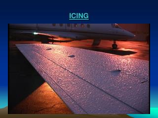
Background • Liquid Water Content: 0.1 to 3 g/m3 • Temperature: = 00 C to -200 C Glaze Ice Encountered During Test (Icing Research Tunnel NASA Glenn) The icing tanker provides simulated test conditions throughout the test envelope required for icing certification (Sikorsky Artificial Icing Tests)
Rotorcraft Icing • Rime Ice: • Low water vapor concentration (0.5 – 1.0 g/m3) • Water droplets freeze on impact • Smooth streamlined, white opaque layers • High surface roughness • Glaze Ice: • High water concentrations (1.5 – 3.0 g/m3) • Water droplets do not freeze upon contact: travel back in • the chord direction • Has a stronger influence on the lift and drag • Irregular ice horns structures created on the leading edge • Rotorcraft Aerodynamics in Icing Conditions • High collection efficiency of rotor: • Higher rotor velocity collects more water droplets • per second (ice accretes under icing conditions) • Vibrations due to mass unbalance • Ice shedding • Premature transition & Separation of flow around the blade • Change in the profile drag over very short periods of time • torque required increase • Undesired vibrations and changes in the handling of the vehicle • flight conditions critically dangerous a) Rime Ice AIRFOIL Temperature, airspeed or liquid water content increase b) Glaze Ice AIRFOIL Typical Rotor Blade Ice Fragments found in the Ground
Anti/De-Icing Solutions For Rotorcraft • ELECTROTHERMAL DE-ICING • Heavy system • Large electrical power consumption • Melted ice may flow aft and refreeze further • Qualified by the FAA and the Dod • Fast erosion of metallic leading-edge protections caps • Substitution by erosion resistant composite plastic leading-edge • Plastic materials have low thermal conductivity • Not suitable to work with thermal de-icing systems due to melting and delamination of the material • PNEUMATIC DE-ICING • Light weight • Inexpensive • High engine torque • requirement • Negligible electrical power requirements • Fast erosion of the blade • leading edge boots • Other Methods Explored: • FLUID ANTI-ICING • ELECTRO-IMPULSE DE-ICING • ELECTRO-VIBRATORY DE-ICING • HIGH FREQUENCY MICROWAVE • ANTI/DE-ICING ICE REMOVAL DURING BOOT INFLATION
Ref: Coffman, H.J., “Helicopter Rotor Icing Protection Methods” • Anti/De-Icing Solutions For Rotorcraft Bell Model 412 (6800 lb) Limited by Fluid on Board Ice Thickness 0.3 in.
Anti-Icing Leading Edge Shear Actuator Conceptual Designs a’ Ω 1 2 Dead Leading Edge Mass (10 – 20% Weight of the Blade) a’ a a’ a a’ Substitute with Shear Piezoelectric Tube Insert Embedded Shear Actuators • Segments poled along longitudinal direction, P2 • Electric field applied in the width direction, E1
Analytical EOM Experimental • Frequency Ranges to Study • 2 Frequency Ranges to Study: 1) Standing wave vibration: 0 Hz up to fifth natural frequency of the system 2) Shear horizontal waves (SHW): 18 KHz up to 20 MHz Dispersion Curves for a 1mm. Think ice layer on an Aluminum Plate Analytical Model and Experimental Results 144 in. AL. Tube Amplitude Response (Deg.) Theoretical calculations (Rose et al): SHW create interface shear stresses of 0.5GPa. Chu et al: typical adhesive shear strength of glaze ice is 0.4MPa 300 Volts input Frequency (Hz)
Initial Approach Standing Wave Vibration a’ Ω PZT Actuator a’ Aluminum Tube
Motivation Icing Static Test PZT Shear Actuator Aluminum Tube Super Cooled Air Radiator Cooper Coil Liquid Nitrogen Bath 20 Psi Pressurized Air
Motivation Icing Static Test FRF: W1 = 436 Hz Amplitude (Deg.) Frequency (Hz) Piezoelectric Actuator
Motivation Icing Static Test Generate a model to efficiently experimentally test the prototype under icing conditions in future work
Summary of Preliminary Studies • Introduction of a new shear induced rotorcraft anti-icing conceptual design • Low weight penalty • No heat degradation of plastic/composite materials • Conduction of icing environment motivation experiments (Vibration Range): • 6’’ Aluminum tube actuated by Shear Tube • Temperature: - 250 C • Ice accretion was prevented by actuator (System 1st natural frequency, standing wave range) • Input voltage of 300 Volts • Strains generated up to 90 μ-strains (Shear Stress of 2.6 MPa) • Formulation and experimental validation of an analytical tool to model the system (Vibration Range) • Uncoupled EOM do not predict the actuators behavior: 1st natural frequency predicted 70% errors • Electrical – mechanical coupled EOM accurately predict the behavior of the actuator • Development of analytical tools for SHW ultrasonic ranges
Proposed Future Work • Experimental validation of predicted ultrasonic shear horizontal wave (SHW) behavior • SHW generate 2 orders of magnitude higher shear stress than standing waves (Vibration Range) • Objective: • Induce horizontal shear waves on a plate using a shear piezoelectric patch • Experimentally observe the generated waves using Electromagnetic Transducers (EMAT) • Experimental selection of optimum frequency and phase velocity for anti-icing purposes • Theoretical calculations predicts that for ice layer thicknesses from 0.3 mm to 0.8 mm, the 2nd mode of the SHW will generate high shear stresses (0.5 GPa), sufficient to affect the ice bounding • Objective: • Form accreted ice to a substrate plate using the liquid nitrogen cooling radiator • Observe the effects of SHW to the ice bounding strength via ice detection system (visual, infrared system, or ultrasonic guided wave (Rose 1999)) • Measurement of generated shear stresses at the ice-substrate interface • Implementation of presented ultrasonic anti-icing system to composite and plastic protection leading edge caps • Cold wind tunnel and hover stand icing testing on proposed ultrasonic induced shear anti-icing system • Cold Chamber with rotor stand at Penn State • Fatigue integrity tests • Delamination of composite rotors • Depoling of shear actuators at larger number of cycles (greater than 2 x 10⁸ cycles)
Ultrasonic SHW Theory • Shear horizontal ultrasonic waves in a solid isotropic elastic media formal solution Wave propagation Displacement Field X1 o Stress Field Ice Eigen values obtained from Christoffel’s Equation Fe X2 X3 Undetermined Coefficients for the Partial Waves K Wave number along the x1 direction Corresponding Phase Velocity of the Wave Solved from Bc’s
Proposed Initial Approach Shear Horizontal Waves SUPERCOOLED AIR FROM LIQUID NITROGEN RADIATOR d15 Shear Motion Poling Direction + EMAT SENSOR ICE - Width Applied Voltage THERMOMETER
Contact: Edward C. Smith ECS5@PSU.EDU
Related References • Coffman, H.J., “Helicopter Rotor Icing Protection Methods,” Bell Helicopter Textron Inc., Fort Worth Texas. Journal of the American Helicopter Society 1987 • Gent, R.W., Dart, N.P., and Candsdale, J.T., “Aircraft Icing,” Defense Evaluation and Research Agency, Farnborough, Hampshire GU14 OLX, UK, The royal Society, 2000 • Flemming, R.J., “The Past Twenty Years of Icing Research and Development at Sikorsky Aircraft,” 40th AIAA Aerospace Sciences Meeting, January 14th 2002 • M.C. Chu, and R.J.Scavuzzo, Adhesive Shear Strength of Impact Ice, AIAA Journal, Vol. 29, No. 11, November (1991), 1921-1926 • Bragg, M.B., Bassar, T., Perkins, W. R., Selig, M. S., Voulgaris, P. G., and Melody, J. W., “Smart Icing Systems for Aircraft Icing Safety,” AIAA Aerospace Science Meeting January 14th 2002 • J. L. Rose and Lvis E. Soley, “Ultrasonic guided wave for anomaly detection in aircraft components”, Material Evaluation, Sep. 2000, 1080-1086 • J. L. Rose, D. D. Hongerholt, G.. Williams, “Ultrasonic In-Flight Ice Detection,” • J. L. Rose, Ultrasonic waves in solid media, Cambridge university press, Cambridge, (1999).