Download
1 / 30
300 likes | 499 Vues
Development of A Near-Infrared Camera for use at RBO. A Preliminary defense by Andy Monson. Motivations for Instrumentation Thesis. Develop NIR camera expertise Cryo-mechanical techniques Electronics and array performance Camera control software NIR observational strategies

E N D
Development of A Near-Infrared Camera for use at RBO A Preliminary defense by Andy Monson
Motivations for Instrumentation Thesis • Develop NIR camera expertise • Cryo-mechanical techniques • Electronics and array performance • Camera control software • NIR observational strategies • Demonstrate camera capabilities • Synoptic photometry of bright stars
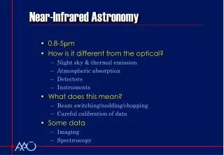
NIR Characteristics • CMOS detectors using HgCdTe have reached 2048x2048 pixels. EXPENSIVE !!! $350,000.00 • Atmospheric H2O absorption defines near-infrared bands • Filters designed to fit in atmospheric windows • Thermal emission from sky dominates past 2.5 microns and emission from OH in atmosphere contributes to flux in H band
What are the benefits of the NIR? • Less sensitivity to extinction • Less sensitivity to heavy metal abundance • Systematic errors are less by an order of magnitude
BIRCAM was developed to gain insight and develop techniques for constructing the mechanics, electronics, and software interfaces for a larger camera currently under development at UW. BIRCAM is a capable instrument in its own right. Buttes Infra-Red CAMera (BIRCAM)
Optical Design • IR cameras need internal optics and a cold stop to prevent thermal background from telescope structure from reaching the detector • Re-imaging optics folded to fit in the dewar using an Offner relay • All mirror design reduced cost, low emissivity and no chromatic aberration • Designed in ZEMAX to determine optimum spacing
Optics Bench • Everything inside the dewar is at -200°C to minimize thermal background. • Designed to minimize effect of thermal contraction. • Allows for each mirror to be tip/tilted and positioned relative to each other for alignment. • The filter wheel (from BABE) mounts to the bench. • A cryo-conditioned stepper motor moves the filter wheel via LabView GUI. • Micro-switches sense the position of the filter wheel mechanically.
Detector Fanout-Board • Provided by John Geary (CfA/Harvard) • Seats the H2 array in ziff socket and fans out signal lines from each quadrant to connector • Heaters and temperature sensor allow for temperature control of the detector. • Enables use of off-chip amplifiers for each of the 32 channels • 128 signals to / from the board to the outside. Wire as fine as hair used for all detector signals.
BIRCAM Interior • Fanout-board is spring loaded and referenced to optical bench • Optics bench mounts to cold plate and squares detector to the optical axis • Cold straps facilitate cooling • CaF2 window protects array. • Temperature sensors on optics bench monitor temperature
Pre-amp & Array Controller • GUMP is a 32 channel, pre-amplifier for providing 5x gain from fanout board to controller (IRLABS). Added resistors to each channel to reference ground. • Controller electronics (Leach / ARC) provides all voltages to array and converts analog signal from GUMP to digital signal to computer. Replaced current limiting resistors to supply adequate power to GUMP and the array • Ground for the controller is isolated from the power supply (different chassis). Huge floating ground problem eliminated by supplying isolated ground from GUMP power supply.
Signal Chain • Developed MultiSim model of signal chain. • Allowed simulation of signal chain • Verification of array performance
Output Waveforms of H2 • 0V(full well) to 0.4V(no light) output from the detector/fanout-board • GUMP applies -3.7V DC offset and 5x gain • Controller applies inverting gain of 5x and A/D offset. • Integrator applies (t/RC)=0.5 gain to 16bit A/D • A/D input = -2.5V(full well) to +2.5V(no light) • Gain = 82,800e/65,536ADU = 1.26e/ADU (theory) • Camera and Electronics Work!
Verification and Testing • Bare CMOS multiplexer provided by Rockwell / Teledyne for testing • Safely verify the electronics • Adjust voltages for 32 independent channels • Adjust bias and offset voltages to tune gain to fit dynamic range of the A/D converters. • Create subroutines to reconstruct (de-interlace) the 32 channels to form an image.
BIRCAM in Cleanroom • BIRCAM during final assembly in the Cleanroom • Clean all surface of fingerprints and other volatiles to minimize outgases in a vacuum • Prevent dust and particulate matter from contaminating the inside.
Hawaii-2 HgCdTe Detector Arrives • 2048 x 2048 array (Rockwell / Teledyne) • 18 micron pixels • CMOS HgCdTe • Full Well 84,000e- • 4 independent quadrants • Capable of 32 channel read-out (8 per quad) • Read out time ~1.3s • QE of 0.85, 0.68, 0.78 at J, H, K
Wiring for BIRCAM • ~100 ft inside dewar (All done here by myself and electronics shop) • ~1000 ft outside dewar (50% done here by myself and electronics shop)
Software for BIRCAM • Voodoo (Java/C) software modified to de-interlace the 32 outputs and write header information and image. • Voodoo configured for Correlated Double Sampling (CDS) • Read array (image1) • Expose • Read array (image2) • Net image = image2 - image1 • LabView GUI developed to control filter wheel position, monitor temperatures and control detector temperature
Cool down at RBO • 30 liters of LN2 brought to RBO every 5 days • It takes about 3 hours to cool the array to 78K and an additional 3 hours for the optics bench to reach 80K • BIRCAM is kept continuously cold to be ready at a moments notice.
BIRCAM at RBO • BIRCAM mounts to telescope through the use of an adapter ‘boot’ • Controller mounts to boot but is electrically isolated from telescope • Power Supplies and external controllers ride on cart next to telescope.
First Light Dec,17 2007 • Field of View = 13x13 arc-minutes, pixel scale = 0.76 “/pix • Optical Image of M42 Orion Star Forming Region from RBO (credit: Chris Rodgers). BIRCAM Near-Infrared view of same region.
BIRCAM Performance at RBO • Linear to 56,000 counts • Gain = 0.95 e- / ADU • Read Noise = 18 e-
Science Opportunities with BIRCAM at RBO • Sensitivity of BIRCAM is comparable to the 2 Micron All Sky Survey (2MASS). • BIRCAM allows for synoptic surveys of relatively bright stars. • Gamma Ray Bursts • Nearby Supernovae • Variable Stars (esp. Cepheid Variables)
Cepheid Variable Stars • More massive more intrinsically luminous Cepheids have longer periods. Plot intrinsic luminosity versus period to obtain the PL relation • Mechanism for pulsation due to opacity (kappa-mechanism) • As star contracts the density and temperature rise • The increase in temperature causes a shell of helium to ionize • Kramers law kappa = density * T^(-3.5), since temperature is driving ionization, the density is the dominant term and the opacity increases. • Radiation is ‘trapped’ in high opacity conditions and the radiation pressure forces the star to expand • As the star expands, the density and temperature decrease. The Helium shell recombines with free electrons and the opacity falls • Radiation ‘flows’ through low opacity conditions and radiation pressure loses to gravity causing contraction.
The Cepheid PL relation • The form of the PL relation is M = a Log(P) + b • Infer the intrinsic luminosity by measuring the period • Compare measured apparent brightness to inferred intrinsic luminosity to determine the distance. • Measured apparent brightness effected by: extinction, line blanketing and binarity. • Observe in the NIR where these systematic effects are small compared to the optical. • Example from http://sci.esa.int
Cepheids and The Distance Ladder • Cepheids will link (via GAIA) trigonometric parallax to tertiary distance indicators (they link relative distance measures to absolute distance measure). • By observing in the NIR, systematic effects are reduced. • Future distances to galaxies will be improved. • Measurements of the Hubble Constant will be better constrained. • See for example: Jacoby etal (1992)
Cepheids observed in the NIR • Samples Based on Cepheids that had known distances based on methods other than trigonometric parallax • Laney & Stobie 1992 • Welch 1984 • Barnes 1997 • A combined total of 59 quality Cepheids
BIRCAM survey • BIRCAM will enable Northern Hemisphere survey of nearly 120 Cepheids in the J, H and K bands with periods between 4 and 40 days. • Well sampled light-curves produces standard NIR templates • The light-curves will provide for a future calibration of the NIR PL relation once GAIA data is available. • Detailed light-curves will enable a comparison to LMC Cepheids to identify systematic differences (if any).
Data Analysis • Simple image reduction techniques (IRAF) • Standard star calibration • NIR standards (Elias) and 2MASS. • Cepheid photometry • Differential aperture photometry of isolated Cepheids and secondary standards • Periods are known • Optimization of phase coverage for each star • Construct template light-curves
Timeline • Fall 2007 : Finish building camera and begin observations at RBO (Complete). Write Instrument paper for PASP. • Spring / Summer 2008 : Continue observing at RBO while reducing data and submit instrument paper. Finish observation and continue to reduce data and begin analysis. Write observations paper for AJ. • Fall 2008 : Complete analysis of light-curves shapes including a comparison with the LMC sample. Start writing results and thesis defense. Finish all tasks and defend thesis.