Download
1 / 19
190 likes | 354 Vues
Positron. Polarized Electron Footprint at JLab. P. Adderley , J. Clark, J. Dumas ǂ , A. Freyberger , J. Hansknecht , J. Grames , M. Poelker, K. Surles -Law, M. Stutzman, R. Suleiman, E. Voutier ǂ. Thomas Jefferson National Accelerator Facility Newport News, Virginia, USA

E N D
Positron Polarized Electron Footprint at JLab P. Adderley, J. Clark, J. Dumasǂ, A. Freyberger, J. Hansknecht, J. Grames, M. Poelker, K. Surles-Law, M. Stutzman, R. Suleiman, E. Voutierǂ Thomas Jefferson National Accelerator Facility Newport News, Virginia, USA ǂLaboratoire de Physique Subatomique et de Cosmologie Grenoble, France
A B C Continuous Electron Beam Accelerator Facility • Recirculating SRF LINACs • Three Halls; 3x the physics Two SRF 600 MeV linacs (1497 MHz) 67 MeV injector (1497 MHz) RF Lasers (499 MHz) RF deflectors A B C Double-sided septum Pockels cell Wien filter Spin Precession Degrees of Freedom P 100 keV DC Electron Gun
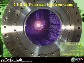
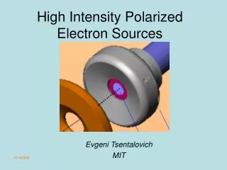
Everyone Gets Polarized Electrons ! • CEBAF’s first polarized e-beam experiment 1995 • Now polarized beam experiments comprise ~ 80% of our physics program, in fact, we only deliver polarized electrons • All beam originates via photoemission from a strained superlattice GaAs crystal inside a 100kV DC photogun • Three experimental areas may simultaneously receive: • high polarization (~85%) • continuous wave (499 MHz) • independent intensity (50 pA to 200 mA) • energy selection (6 GeV now, 12 GeV 2012) • What about positron physics ? • Lepton charge degree of freedom • But, costly endeavor… • But, rich e- program keeps us busy…
JPOS’09 Recent workshop to discuss e+ @ Jlab … identified “old” & newphysics motivations… • GeneralizedParton Distributions • Investigation of 2g exchange in elasticscattering • Study of Coulomb distortion in the inelasticregime • Search for a light darkmatter gauge U-boson • Measurement of the C3qneutralweakcoupling • Positron Annihilation Spectroscopy • e+beamcurrent > 100 nAin CW mode • As large as possible e+beampolarization New interest from the source & accelerator community working at JLab …
If the shoe fits … …then wear it ! 10 MeV/10 mA Power loss/scattering Compact, low rad 100 MeV/10 mA Better divergence Worse energy spread 1000 MeV/1 mA Easier source Bigger “driver” A. Freyberger, Proc. of the International Workshop on Positrons at Jefferson Lab, Newport News (VA, USA), March 25-27, 2009
R&D Effort for a continuouswave[polarized] positron source atJLab for fixedtargetexperimentsto take place in the 12 GeVera. J. Dumas, C. Hyde, T. Forest, A. Freyberger, S. Golge, J. Grames, R. Kazimi, E. Voutier S. Golge et al., Proc. of the International Workshop on Positrons at Jefferson Lab, Newport News (VA, USA), March 25-27, 2009 • A possible conceptinvolves the construction of a dedicatede+ tunnelat the end of the injector andparallel to the northlinac. • Positrons wouldbeproducedwith120 MeV e- (JLab 12 GeV) incident on a tungstentarget. • e+’s are selectedwith a quadrupole triplet and transported to the accelerator section. G4beamline simulations indicate a global efficiency of 10-5 e+/e- for 120 MeV e- off a 3 mm W target. 10 mA e-→ 100 nA e+
Polarized Bremsstrahlung/Pair Creation e- g e+ e- E.G. Bessonov, A.A. Mikhailichenko, EPAC (1996) A.P. Potylitsin, NIM A398 (1997) 395 • Within a high Z target, longitudinallypolarized e-’sradiatecircularlypolarizedg’s. • Within the same/differenttarget, circularlypolarizedg’screatelongitudinallypolarized e+’s. So, why not pursued so far … ? Brem Pair bulk GaAs Strained GaAs Superlattice GaAs Pe- 35% 85% 35% 75% 75% 85% 85% 1995 1998 1999 2000 2004 2007 2010 30 mA 150 mA 1 mA 100 mA 50 mA 100 mA 180 mA Ie- All operating with suitable photocathode lifetime to sustain weeks of operation Evolution of CEBAF polarizedelectron source
PhD Thesis: Polarized Positrons for JLab, Jonathan DUMAS Advisors: Eric Voutier, LPSC and Joe Grames, JLab Conventional un-polarized e+ Scheme (bremsstrahlung photon) ILC Polarized e+ Schemes/Demos (synchrotron/Compton polarized photon) OR • E = 50 GeV L = 1m E-166 Experiment High Polarization, High Current e- Gun (polarizedbremsstrahlung photon) T. Omori, Spin 2006 • Positron Yield scales with Beam Power • Replace GeV-pulsed with MeV-CW • Reduce radiation budget • Remain below photo-neutron threshold • Bunch/Capture to SRF linac • Compact source vs. Damping Ring • Unique capabilities • First CW source with helicity reversal
e+ Source Polarization • Simulation are performedwithin the GEANT4framework, takingadvantage of the polarizationcapabilitiesdeveloped by the E166 Collaboration. • The source files are modified to select completescreening (where T~0 or T~60 MeV) R. Dollan, K. Laihem. A. Schälicke, NIM A559 (2006) 185 Polarized Bremsstrahlung Polarized Pair Creation H.A. Olsen, L.C. Maximon, Phys. Rev. 114 (1959) 887.
e+ Figure of Merit (FOM) • The Figure of Meritis the quantity of interest for the accuracy of a measurementwhich combines the incident flux of particles and itspolarization. Optimum FoM Optimum energy
FOM Evolution vs. e- Energy (0 to 60 MeV) • Simplisticcuts are applied to mimic a capture system and the acceleratoracceptance. Thicknesssensitivityisunderstudy…
Demonstration Experiment • An experiment to test the production of polarized positrons iscurrentlydesigned. The goals are to measure the yield and polarizationdistributrions as a function of the beamenergy. • The ATF/KEK & E166successfulset-up serves as a conceptual guidancetowards the final design. • Polarimetry wouldconsist of a Compton transmission polarimeter. • Calibration and check of the analyzing power canbeperformedwith the polarizedelectronbeam. • The Compton asymmetrywouldbemeasured by reversing the beam (up to 1 kHz frequency of random change) and/or the targetpolarization. G. Alexander et al, PRL 100 (2008) 210801 G. Alexander et al, physics.ins-det:0905.3066 ATF/KEK: M. Fukuda et al. PRL 91 (2003) 164801 T. Omori et al. PRL 96 (2006) 114801
Compton Transmission Polarimeter Detector solid angle = +/- 8° W Pg, circ=100% e+ photons • Average asymmetry for Pg,circ=10%
What about CEBAF 10 MeV injector at milliamps? ex,y filter 100kV Gun ez filter SRF • Operating at higher gun voltage… • Improves transmission (stiffer beam) • May improve photocathode lifetime • For high bunch charge guns (like ILC/CLIC) • Essential to overcome photoemission limit
Field Emission – Critical Issue for Higher Voltage “Inverted” no SF6 and no HV breakdown outside chamber “Conventional” cathode electrode mounted on metal support structure Stainless Steel (vs. gap) Niobium (50 mm gap) 5 MV/m Work of Ken Surles-Law, Jefferson Lab Thanks to P. Kneisel, L. Turlington, G. Myneni
“Inverted” Gun • Conventional Ceramic • Exposed to field emission • Large area • Expensive (~$50k) Medical x-ray technology e- • New Ceramic • Compact • ~$5k NEG modules too close New design Want to move away from “conventional” insulator used on allGaAsphotoguns today – expensive, months to build, prone to damage from field emission.
New CEBAF “Inverted” Polarized e- Gun • Installed July-August: • Vacuum => extractor ~3E-12 Torr, IP ~20pA • HV Process to 110kV => no FE or VAC activity • New HVPS => Increased to 150kV supply • New Photocathode => QE>1% and P~85% • Just began running about a week ago. • We’ll begin characterizing lifetime & photocathode…