Download
1 / 40
400 likes | 421 Vues
Discover the progress in polarized electron gun technology over the past two decades. Explore the evolution, challenges, and new materials used in creating reliable and high-quality electron sources. Learn about GaAs photocathodes, strained crystal structures, and semiconductor band structures.

E N D
High Intensity Polarized Electron Sources Evgeni Tsentalovich MIT
Progress over past two decades • Unreliable guns at development stage • Dreams to exceed 40% polarization 15 years ago Now • Routinely operated productive quality guns (SLAC, JLAB, Mainz, Bates…) • Strained, superlattice crystals with polarization approaching 90% • New photocathode materials • New gun concepts
New requirements New generation of accelerators (eRHIC, ILC) demand polarized injectors with extreme parameters • Very high current • Very high polarization • Low emittance Another application: Energy Recovery Linac (ERL) • Very high current • No polarization • Very low emittance
GaAs photocathodes Requirements: high QE and polarization • Remains the only material for polarized electron guns • Very high QE • Very high polarization • But ! Very demanding technology ( Ultra-high vacuum requirements)
- low - medium - high Semiconductor band structure E Conductingband Band gap Valence band Doping (Z, Be) is used to control the concentration of carriers:
-1/2 1/2 3 1 -3/2 -1/2 1/2 3/2 -1/2 1/2 Band structure of GaAs Conductingband E 1.6 eV 0.3 eV k
3 1 Strained crystal E -1/2 1/2 1.6 eV -3/2 3/2 -1/2 1/2 -1/2 1/2 0.3 eV k
Strained GaAs: GaAs on GaAsP 100 nm 100 nm QE ~ 0.15% Pol ~ 75% GaAs-based photocathodes Superlattice GaAs: Layers of GaAs on GaAsP Bulk GaAs 14 pairs QE ~ 0.8% Pol ~ 85% High QE ~ 1-10% Pol ~ 35-45%
Cs, O(F) deposition Negative electron affinity Most (but not all!) electrons reaching the surface are thermolized E Conductive band Vacuum level Band gap (forbidden zone) Valence band surface x
Photocathodes degradation Poisoning by residual gases Ion bombardment • Oxygen- and carbon-containing species are more harmful • Hydrogen and noble gases are more tolerable • This degradation can be healed by heat-cleaning at moderate temperatures (<550 C) • Most harmful • Only high-temperature (~600C) heat cleaning restores QE, and only partially • Effect is proportional to pressure in the chamber and to average current
Charge saturation E Vacuum level surface x
Charge saturation (SLAC data) High doping →low polarization !
High ( )doped layer ~ 5 nm High gradient doping • Works very well • The high-doped layer is thin enough to preserve high polarization • Charge saturation is highly suppressed (at least for fresh crystals) • The top layer can survive only few high-temperature (~600 C) activations • Might be problematic for high-current guns Superlattice Buffer Substrate
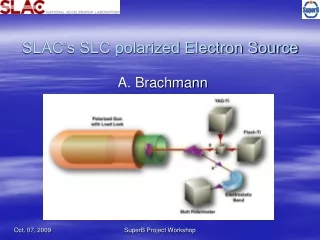
r' r Emittance: DC gun design Cylindrical symmetry Cathode Anode Normalized emittance doesn’t change with acceleration
DC gun design Infinitely small beam spot, no space charge, no nonlinear transverse forces r' r Emittance: Cathode
With perfectly linear transverse forces only thermal emittance remains DC gun design Finite beam spot, no space charge, no nonlinear transverse forces r' r Emittance: Cathode
Nonlinearity in the gun optics may introduce the emittance growth. r' r r' r Emittance: Emittance: Neglecting thermal emittance r' r Emittance: Cathode
J J J J r r r r J J r r Space charge Cathode Anode Space charge may change the beam profile and increase the beam emittance J J J J r r r r Emittance growth might be suppressed by shaping the laser profile
Space charge • Space charge effects are strongest when electrons have low energy (no space charge effects for relativistic beam) • Accelerate as fast as possible – high gradient in the gun • Accelerate as high as possible – high gun voltage, to reduce space charge effects between the gun and the accelerator
Limited (breakdowns) Non-linear transverse forces Space charge Worst case scenario: large emitting spot AND high current density Child’s law: - microperveance; d – distance between cathode and anode Space charge influence: Space charge effects could be reduced by • Increasing gun voltage • Reducing cathode – anode gap • Increasing the emitting spot
Emittance: • Thermal GaAs cathode (room temperature) ~0.2 mm·mrad ·R(mm) • Thermal Cu, Cs2Te cathodes ~1.2 mm·mrad ·R(mm) • Real gun with small emitting spot (JLAB) ~ 5 mm·mrad • Real gun with large emitting spot (Bates) ~15 mm·mrad • Beam after RF chopping/bunching ~ 20-100 mm·mrad • Estimations for RF (SRF) gun ~ 1-5 mm·mrad • ILC requirements ~ .05 mm·mrad
Polarized electron guns: DC RF Approved technology (at least for ~ 100 kV) No working GaAs-based RF gun yet Require RF chopping/bunching Beam from the gun is bunched RF bunching could be avoided with appropriate laser system High acceleration rate, high electron energy from the gun Low energy beam (space charge! ) Better suited for large emitting spot BEST FOR CONVENTIONAL APPLICATIONS OR WHEN VERY HIGH CURRENT IS NEEDED BEST FOR APPLICATIONS WITH VERY HIGH BRIGHTNESS AND LOW EMITTANCE
DC Guns: Mainz V = 100 kV Active spot .25 mm
DC Guns: JLAB V = 100 kV Active spot 0.2 mm
DC Guns: Bates V = 60 kV Active spot 12 mm
DC Guns: SLAC V = 120 kV Active spot 15 mm
DC Guns: Nagoya V = 200 kV Active spot 18 mm
DC Guns: Cornell V = 500 kV (800 ? )
RF guns • The only practical experience: BINP (Novosibirsk) • Good vacuum conditions with RF on and unactivated GaAs crystal installed • Activated GaAs crystal survived just several RF cycles • Severe back-bombardment resulted in a very short life time
RF guns (SLAC) 1.6 cell pill box Higher Order Mode (HOM) single cell • More open structure • No internal irises • More effective vacuum pumping
Much easier to do Better chances of success RF guns: Warm SRF Very expensive and untested technology Significant practical experience Unclear if GaAs-based cathode will survive RF gun conditions Best vacuum possible New, more robust cathode materials may appear (GaN) Wide open apertures (eliminates back bombardment)
Laser development Fiber lasers: • Very short pulses • Mode – locked, but rep. rate limited to MHz • Wavelength 1030 – 1500 nm, but could be frequency-doubled • Reliable • Relatively expensive
Laser development Elliptical beams (SLAC) • Suppression of non-linear space charge effects • Maximizing brightness • Might be very useful for RF guns • Very challenging task
ILC gun • DC or RF gun could be used • ILC emittance requirements are so high that even RF gun is unlikely to meet them without dumping ring • Although dumping ring is still required for RF gun, it might be of much simpler design, saving millions • Conclusion: RF gun would be a better option, but it requires significant R&D and the success is not guaranteed
eRHIC gun (ring-ring) • Modest intensity and emittance requirements • Regular DC gun is well suited for the task • Two options: mode-locked laser or RF chopper/buncher Polarized electron gun for ring-ring eRHIC version is based on proven technology and doesn’t require any significant R&D • Mode-locked laser: • Simplifies injector • No emittance growth in chopper • RF chopper/buncher: • Complicates injector • Emittance growth in chopper • Beam compression reduces peak current demand from the gun
eRHIC gun (linac-ring) Extremely high current demand !!! I(average) ~ 500 mA I(peak) ~ 200 A High polarization → strained GaAs → QE ~ 0.1% Average laser power ~ 800 W Such lasers do not exist. Possible solutions: a) array of diode lasers b) dedicated FEL – almost unlimited laser power, tunable
HEAT GaAs t=1 mm ACTIVE COOLING With a conventional cathode stalk system, the cathode would heat up to stellar temperatures, but, fortunately, melt first. Problems without known solution Heat load (800 W on the cathode) New problem: dynamic cooling (gun off !)
For DC gun : Emitting spot : Problems without known solution Peak current (~200 A) Larger cathodes? Ring-like cathodes ? What about emittance ???
Can we relax the requirements? • With I(average) ~ 40-50 mA the luminosity is the same as in ring-ring version • 40-50 mA gun is still a very difficult task, but it is a LOT easier than 500 mA • Heat load and perveance problems go away • Life time of the cathode is still a major problem