Download
1 / 15
150 likes | 191 Vues
This presentation delves into the prospects of polarized electron sources for modern accelerator designs, touching on the challenges and advancements observed in the field. From discussing gun issues in new high current CW machines to exploring factors affecting gun lifetime and vacuum improvement, the talk navigates through intricacies like charge limits, laser power, and peak current requirements. By presenting insights on gun lifetime estimates, improving gun vacuum, laser performances, and their associated challenges with meeting pulse structure demands, the session aims to provide a comprehensive overview of the evolving landscape of electron sources for cutting-edge collider technologies.

E N D
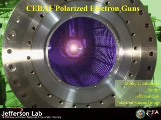
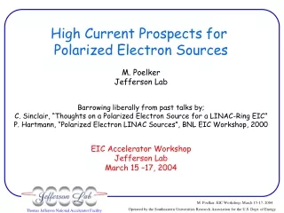
High Current Prospects for Polarized Electron Sources M. Poelker Jefferson Lab Barrowing liberally from past talks by; C. Sinclair, “Thoughts on a Polarized Electron Source for a LINAC-Ring EIC” P. Hartmann, “Polarized Electron LINAC Sources”, BNL EIC Workshop, 2000 EIC Accelerator Workshop Jefferson Lab March 15 –17, 2004
JLab FEL program with unpolarized beam ELIC with circulator ring Ave. Beam Current (mA) First low polarization, then high polarization at CEBAF Year Source requirements for ELIC less demanding with circulator ring. Big difference compared to past talks. Few mA’s versus >> 100 mA of highly polarized beam. First polarized beam from GaAs photogun Continuing Trend Towards Higher Average Beam Current
Gun Issues for New High Current CW Machines ~ 100 mA Unpolarized Beam for Light Sources ( e.g., JLab FELs and Cornell ERL) and Cooler Rings • Unpolarized beam so bulk GaAs OK • Expect 10% QE at 532 nm; • 4.3 mA/W/%QE • ~ 6 W provides 1/e operation at 100 mA • 10 W commercial doubled Nd:YAG lasers with rep rates to 100 MHz are available. • Higher rep rates requires laser R&D (SESAMs, Ti-Saps) • Lifetime? Probably wise to improve vacuum (more later) • Charge Limit? No (bunch charge < 1 nC). Also, not a big problem with heavily doped bulk GaAs and high QE. • Gun HV ~ 500 kV to mitigate emittance growth. • Must limit field emission.
Gun Issues for New Pulsed Machines Electron-Positron Colliders; NLC, JLC, CLIC, TESLA • Polarization 80%, Photocathode QE only 0.1 to 1%. • Very high peak current but low average current (< 30uA), so low QE not a problem. • Expect good lifetime with present vacuum technology. • Charge Limit? Yes, at nC bunch charge. Heavily doped photocathode surface helps (but tough to keep heavily doped surface after repeated activations). • Peculiar laser pulse structures; microstructure within macrostructure. Large micropulse width and low rep rate for TESLA. R&D required.
ELIC e-Beam Specifications 1/f C /c /c ~100 C c I CR CR Injector C = 1.5 km t I CR Circulator Ring t • Typical parameters; • Ave injector gun current 2.5 mA (and then 25 mA) • Micropulse bunch charge 1.6 nC • Micropulse rep rate 150 MHz (and then 1.5 GHz) • Macropulse rep rate ~ 2 kHz, 0.5 ms duration.
Gun Issues for ELIC • Need 80% polarized e-beam. • Use SVT superlattice photocathode. 1% QE at 780 nm; • 6.3 mA/W/%QE • ~ 1 W provides 1/e operation at 2.5 mA • Commercial Ti-Sapp lasers with CW rep rates to 500 MHz provide 0.5 W. Homemade lasers provide ~ 2W. • Injector micropulse/macropulse time structure demands laser R&D. • 25 mA operation requires more laser power and/or QE. • Charge Limit? Yes, at 1.6 nC/bunch and low QE wafers. • Lifetime? Probably wise to improve vacuum (more later) • Gun HV ~ 500 kV to mitigate emittance growth. • Must limit field emission.
Gun Lifetime • CEBAF enjoys good gun lifetime; • ~ 200 C charge lifetime (until QE reaches 1/e of initial value) • ~ 10,000 C/cm2 charge density lifetime (we operate with a ~ 0.5 mm dia. laser spot) • Gun lifetime dominated by ion backbombardment. • So it’s reasonable to assume lifetime proportional to current density. • Use a large laser spot to drive ELIC gun. This keeps charge density small. Expect to enjoy the same charge density lifetime, despite higher ave. current operation, with existing vacuum technology.
Gun Lifetime cont. Lifetime Estimate; • Use 1 cm diameter laser spot at photocathode. • At 2.5 mA gun current, we deliver 9 C/hour, 216 C/week. • Charge delivered until QE falls to 1/e of initial value; • Need to test the scalability of charge lifetime with laser spot diameter. Measure charge lifetime versus laser spot diameter in lab. 10,000 C/cm2 *1 Wk/216 C * 3.14(0.5 cm)^2 = 36 Wks! 3.6 Weeks lifetime at 25 mA.
Improving Gun Vacuum Ultimate Pressure = Outgassing Rate x Surface Area Pump Speed 304 SS 316L SS Aluminum CEBAF gun vacuum ~ 1e10-11 Torr. Reasonable to expect order of magnitude improvement. We need; Smaller outgassing rate, Less surface area, More pump speed. Work by Adderley, Stutzman
Laser Power and Max QE • Present state of the art; • QE = 1% at ~ 80% polarization (SVT superlattice photocathode) • TimeBandwidth SESAM modelocked Ti-Sapphire laser with rep rates to 500 MHz and ave. power ~ 500 mW • “Homemade” modelocked Ti-Sapphire laser with rep rates to ~ 3 GHz and ave. power ~ 2 W (C. Hovater and M. Poelker, Nucl. Instr. And Meth. A418, 280 (1998). • We should be able to deliver 12.6 mA today! Albeit with a CW pulse structure.
Laser Power and Max QE Problems • My 2 W laser does not meet ELIC pulse structure requirements. • How to generate required peak power? 100 W peak power to meet 2.5 mA spec. Tough job! • High power diode lasers might create macropulse but can’t turn ON/OFF fast enough to create micropulses. Maybe use rf cavities to create microstructure? (M. Farkhondeh, this workshop) • Can we build Q-switched, modelocked Ti-Sapphire laser with ~ 2 kHz macropulse structure and 1 W ave. power?
Charge Limit Problems 5x10¹⁸/cm3 2x10¹⁹ /cm3 doping density • Charge accumulates at surface and opposes photoemission. QE drops with increasing laser power. Problem at high bunch charge (~ nC). • What to do? • Use high dopant density at surface. But dopant diffuses after repeated heat and activation cycles. • Use big laser spot to minimize charge density. T. Maruyama et al., SPIN 2002 Proceedings, Workshop on Polarized Electrons Sources and Polarimeters, MIT Bates
Suppressing Field Emission Field emission from a 1 mm finish bare SS electrode Field emission from a 9 mm finish SS electrode treated by PSII 28 mA at 15 MV/m 170 pA at 30 MV/m I (mA) I (pA) E (MV/m) E (MV/m) (necessary to preserve vacuum and prolong operating lifetime of gun. Easy at 100 kV. A bit more difficult at 500 kV) Studies on flat SS electrodes show that field emission is greatly reduced by Plasma Source Ion Implantation From C. K. Sinclair, H. F. Dylla, T. L. Siggins, D. Manos, L. Wu, and T. J. Venhaus, Proceedings of the 2001 Particle Accelerator Conference, Chicago, IL, p.610.
Summary • As with past speakers, I’ve assumed emittance is not an issue. • Circulator Ring reduces demands on photogun. Good news! Ave. gun current between 2.5 and 25 mA instead of 250 and 2500 mA. As a result, expect good lifetime with existing vacuum technology (although vacuum improvements wouldn’t hurt…). • We still have significant laser issues. Thanks to the circulator ring, we have more modest average power requirements but we still have very high peak power requirements. It’s a tough job to create necessary laser pulse structure. • Alternate circulator filling schemes?
Summary cont. • Chalcopyrite photocathodes are still worth studying. High polarization and QE comparable to bulk GaAs (in theory). Samples from A. Rockett of UofI in-house. • Charge limit problems? Work of Nagoya, SLAC groups suggest there will be problems. Need to study. • Modest engineering challenges to be overcome; photocathode cooling, load-lock gun design, HV ceramic issues, cryopumping?, vacuum chamber diffusion coatings to limit outgassing, … • Jlab Source Group excited about conducting high current (~ mA), high polarization tests. We have tools in house; SVT superlattice photocathodes, 2 W homemade modelocked Ti-Sapp laser, 100 kV loadlocked gun and beamline.