D1200757 Sequencer – Insertable
D1200757 Sequencer – Insertable.


D1200757 Sequencer – Insertable
E N D
Presentation Transcript
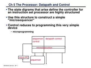
D1200757 Sequencer – Insertable Input is from 4 (four) DC Power Supplies: +24VDC, -24VDC, +18VDC, and -18VDC. This sequencer prohibits the 18V supplies from being present prior to the 24V supplies. When the ON/OFF Switch is in the ON position, +24 and -24 are passed to the Output side, and the internal relay switches are closed so that +18 and -18 are passed to the Output side as well. The relays are operated independently. The +24VDC controls the +18VDC and the -24VDC controls the -18VDC. Output is intended to go to two standard power strips: 0ne +- 24VDC strip and one +-18VDC strip.
Sequencer – On/Off Switch SW-3831
Sequencer – Relay D06D100
Sequencer – Connectors 3003W3SXX99A30X
Sequencer – Connectors 3003W3PXX99A30X 3003W3PXX99A30X are ordered directly from CONEC. It is unusual to have plugs that are panel mounted, but not unheard of. These boxes are intended to be insertable, and thus require these connectors.
Sequencer – Connectors 303W3CSXX99A30X
Sequencer – Connectors 303W3CPXX99A30X 303W3CPXX99A30X are ordered directly from CONEC. It is unusual to have plugs that are panel mounted, but not unheard of. These boxes are intended to be insertable, and thus require these connectors.
Sequencer – Jack Sockets MDVS44-ND (3341-1S) x 4 (Kit)
Sequencer – LED 5100-H5 x 8
Sequencer – Current Regulator Diode 1N5314 x 8
Sequencer – Zener Diode 2EZ18D5MSCT-ND x 2 DIODE ZENER 18V 2W DO-41
Sequencer – Screws and Nuts for Relays 91099A266 91831A009 x 4 x 4
Sequencer – Spade Terminals for LEDs 69145K69 Crimp-on Spade Terminal Block, Vinyl Insulated, 22-18 AWG, #10 Stud x 4
Sequencer – Spade Terminals for Wires 69145K78 Crimp-on Spade Terminal Block, Vinyl Insulated, 12-10 AWG, #10 Stud x 8
Sequencer – Wire Nuts 7108K6 x2
Sequencer – Butt Splice 7227K12 x 1
Sequencer – Layout – Side View Box 7” (4U) x 7” (4U) x 3” Relay In Plugs Out Sockets Switch (Front) (Rear) Bottom Plate 8.75” (5U)
Sequencer – Layout – ‘In’ View (Front) Box 7” (4U) x 7” (4U) x 3” Input 0.5” 0.5” +24 -18 -24 +18 On Center at 5.25 x 2.25” Center at 1.25 x 2.25” Switch Center at 1.5” x 1.5” Off Center at 5.5” x 1.5” LIGO-D1200757 DC Power Sequencer Center at 3.5” x 1.5” (0,0) Bottom Plate 8.75” (5U)
Sequencer – Layout – ‘Out’ View (Rear) Box 7” (4U) x 7” (4U) x 3” Output 0.5” 0.5” +24 -24 -18 +18 Center at 5.25 x 2.25” Center at 1.25 x 2.25” Center at 1.5” x 1.5” Center at 5.5” x 1.5” LIGO-D1200757 DC Power Sequencer (0,0) Bottom Plate 8.75” (5U)
Sequencer – Layout – Box Bottom Inches Rack Units Hole pattern for Box Bottom: 8 – 6-32 PEM Nuts arranged so that the Bottom Plate can mate with the Box at both 0 degrees and 90 degrees rotation Out In Box 7” (4U) x 7” (4U) x 3” (0,0) Inches
Sequencer – Layout – Box Top Inches Hole pattern for Box Bottom: 4 – holes as per diagram, – countersunk for 8/32 Phillips flathead screws 1.87” Center to Center Relay 1 Center at 5.0” x 5.0”” Out In Relay 2 Center at 5.0” x 2.0”” Box 7” (4U) x 7” (4U) x 3” (0,0) Inches
Sequencer – Layout – Bottom Plate Inches Bottom Plate 8.75” (5U) Rack Units Hole pattern for Bottom Plate: 8 - ¼” holes centered ¼” from edge and centered at the center of every 1U (Rack Unit) 8 – holes arranged so that the Bottom Plate can mate with the Box at both 0 degrees and 90 degrees rotation – countersunk for 6/32 Phillips flathead screws Out In Box 7” (4U) x 7” (4U) x 3” Inches
Hole Pattern for Rack Units Rack Units Inches 0.625 0.625 0.500 0.000 0.250 1.750 1.500 0.875 0.250 (¼”) holes centered at: 0.000 + 0.250 = 0.250 0.000 + 0.875 = 0.875 0.000 + 1.500 = 1.500 1.750 + 0.250 = 2.000 1.750 + 0.875 = 2.375 1.750 + 1.500 = 3.250 3.500 + 0.250 = 3.750 3.500 + 0.875 = 4.365 3.500 + 1.500 = 5.000 5.250 + 0.250 = 5.500 5.250 + 0.875 = 6.125 5.250 + 1.500 = 6.750 7.000 + 0.250 = 7.250 7.000 + 0.875 = 7.875 7.000 + 1.500 = 8.500 8.750 + 0.250 = 9.000 8.750 + 0.875 = 9.375 8.750 + 1.500 = 10.250
Sequencer – Layout – Bottom View Inches Inches Plugs Sockets 4 1 -18 -18 A3 A3 A2 A2 Relay 1 A1 A1 +18 +18 +3 +2 9 7 8 Switch In 6 4 5 Out 3 1 2 4 1 -24 -24 Relay 2 A3 A3 A2 A2 +24 A1 A1 +24 +3 +2 Inches
Sequencer – Layout – Labels Input Output +24 -18 +18 -24 -24 +18 -18 +24 On Off LIGO-D1200757 DC Power Sequencer LIGO-D1200757 DC Power Sequencer Silk screen labels. Please note carefully the LED labels.
Sequencer – Wiring 2EZ18D5 1N5314