Ch 5 The Processor: Datapath and Control
sequencer control. datapath control. microinstruction. micro-PC. sequencer. Ch 5 The Processor: Datapath and Control. The state digrams that arise define the controller for an instruction set processor are highly structured Use this structure to construct a simple “microsequencer”

Ch 5 The Processor: Datapath and Control
E N D
Presentation Transcript
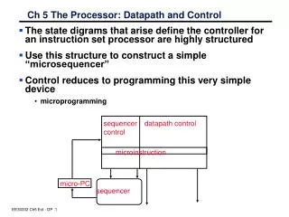
sequencer control datapath control microinstruction micro-PC sequencer Ch 5 The Processor: Datapath and Control • The state digrams that arise define the controller for an instruction set processor are highly structured • Use this structure to construct a simple “microsequencer” • Control reduces to programming this very simple device • microprogramming
Recap: Microprogram Control Specification – control field for each control point in the machine µseq µaddr A-mux B-mux bus enables register enables
How Effectively are we utilizing our hardware? IR <- Mem[PC] • Example: memory is used twice, at different times • Ave mem access per inst = 1 + Flw + Fsw ~ 1.3 • if CPI is 4.8, imem utilization = 1/4.8, dmem =0.3/4.8 • We could reduce HW without hurting performance • extra control A <- R[rs]; B<– R[rt] S <– A + B S <– A or ZX S <– A + SX S <– A + SX M <– Mem[S] Mem[S] <- B R[rd] <– S; PC <– PC+4; R[rt] <– S; PC <– PC+4; R[rd] <– M; PC <– PC+4; PC <– PC+4; PC < PC+4; PC < PC+SX;
Microprogramming • Control is the hard part of processor design ° Datapath is fairly regular and well-organized ° Memory is highly regular ° Control is irregular and global Microprogramming: -- A Particular Strategy for Implementing the Control Unit of a processor by "programming" at the level of register transfer operations Microarchitecture: -- Logical structure and functional capabilities of the hardware as seen by the microprogrammer Historical Note: IBM 360 Series first to distinguish between architecture & organization Same instruction set across wide range of implementations, each with different cost/performance
State Reg Sequencer-based control unit Control Logic Multicycle Datapath Outputs Inputs Types of “branching” • Set state to 0 • Dispatch (state 1) • Use incremented state number 1 Adder Address Select Logic Opcode
“Macroinstruction” Interpretation User program plus Data this can change! Main Memory ADD SUB AND . . . one of these is mapped into one of these DATA execution unit AND microsequence e.g., Fetch Calc Operand Addr Fetch Operand(s) Calculate Save Answer(s) CPU control memory
Variations on Microprogramming ° “Horizontal” Microcode – control field for each control point in the machine ° “Vertical” Microcode – compact microinstruction format for each class of microoperation – local decode to generate all control points branch: µseq-op µadd execute: ALU-op A,B,R memory: mem-op S, D µseq µaddr A-mux B-mux bus enables register enables Horizontal Vertical
Extreme Horizontal 3 1 input select . . . N3 N2 N1 N0 1 bit for each loadable register enbMAR enbAC . . . Incr PC ALU control Depending on bus organization, many potential control combinations simply wrong, i.e., implies transfers that can never happen at the same time. Makes sense to encode fields to save ROM space Example: mem_to_reg and ALU_to_reg should never happen simultenously; => encode in single bit which is decoded rather than two separate bits NOTE:encoding should be just sufficient that parallel actions that the datapath supports should still be specifiable in a single microinstruction
More Vertical Format next states inputs src dst other control fields MUX D E C D E C Some of these may have nothing to do with registers! Multiformat Microcode: 6 1 3 Branch Jump 0 cond next address 1 3 3 3 1 dst src alu Register Xfer Operation D E C D E C
Hybrid Control Not all critical control information is derived from control logic E.g., Instruction Register (IR) contains useful control information, such as register sources, destinations, opcodes, etc. enable signals from control Register File R S 1 D E C R S 2 D E C R D D E C rs1 IR op rs2 rd to control
Vax Microinstructions VAX Microarchitecture: 96 bit control store, 30 fields, 4096 µinstructions for VAX ISA encodes concurrently executable "microoperations" 95 87 84 68 65 63 11 0 USHF UALU USUB UJMP 001 = left 010 = right . . . 101 = left3 010 = A-B-1 100 = A+B+1 00 = Nop 01 = CALL 10 = RTN Jump Address ALU Control Subroutine Control ALU Shifter Control
Horizontal vs. Vertical Microprogramming NOTE: previous organization is not TRUE horizontal microprogramming; register decoders give flavor of encoded microoperations Most microprogramming-based controllers vary between: horizontal organization (1 control bit per control point) vertical organization (fields encoded in the control memory and must be decoded to control something) Vertical + easier to program, not very different from programming a RISC machine in assembly language - extra level of decoding may slow the machine down Horizontal + more control over the potential parallelism of operations in the datapath - uses up lots of control store
Designing a Microinstruction Set 1) Start with list of control signals 2) Group signals together that make sense (vs. random): called “fields” 3) Places fields in some logical order (e.g., ALU operation & ALU operands first and microinstruction sequencing last) 4) Create a symbolic legend for the microinstruction format, showing name of field values and how they set the control signals • Use computers to design computers 5) To minimize the width, encode operations that will never be used at the same time
1&2) Start with list of control signals, grouped into fields Signal name Effect when deasserted Effect when assertedALUSelA 1st ALU operand = PC 1st ALU operand = Reg[rs]RegWrite None Reg. is written MemtoReg Reg. write data input = ALU Reg. write data input = memory RegDst Reg. dest. no. = rt Reg. dest. no. = rdTargetWrite None Target reg. = ALU MemRead None Memory at address is readMemWrite None Memory at address is written IorD Memory address = PC Memory address = ALUIRWrite None IR = MemoryPCWrite None PC = PCSourcePCWriteCond None IF ALUzero then PC = PCSource Single Bit Control Signal name Value EffectALUOp 00 ALU adds 01 ALU subtracts 10 ALU does function code 11 ALU does logical OR ALUSelB 000 2nd ALU input = Reg[rt] 001 2nd ALU input = 4 010 2nd ALU input = sign extended IR[15-0] 011 2nd ALU input = sign extended, shift left 2 IR[15-0] 100 2nd ALU input = zero extended IR[15-0] PCSource 00 PC = ALU 01 PC = Target 10 PC = PC+4[29-26] : IR[25–0] << 2 Multiple Bit Control
Start with list of control signals, cont’d • For next state function (next microinstruction address), use Sequencer-based control unit from last lecture • Called “microPC” or “µPC” vs. state register Signal Value EffectSequen 00 Next µaddress = 0 -cing 01 Next µaddress = dispatch ROM 10 Next µaddress = µaddress + 1 1 microPC Adder Mux 2 1 0 0 µAddress Select Logic ROM Opcode
3) Microinstruction Format: unencoded vs. encoded fields Field Name Width Control Signals Set wide narrow ALU Control 4 2 ALUOp SRC1 2 1 ALUSelA SRC2 5 3 ALUSelB ALU Destination 6 4 RegWrite, MemtoReg, RegDst, TargetWr. Memory 4 3 MemRead, MemWrite, IorD Memory Register 1 1 IRWrite PCWrite Control 5 4 PCWrite, PCWriteCond, PCSource Sequencing 3 2 AddrCtl Total width 30 20 bits
4) Legend of Fields and Symbolic Names Field Name Values for Field Function of Field with Specific ValueALU Add ALU adds Subt. ALU subtracts Func code ALU does function code Or ALU does logical ORSRC1 PC 1st ALU input = PC rs 1st ALU input = Reg[rs]SRC2 4 2nd ALU input = 4 Extend 2nd ALU input = sign ext. IR[15-0] Extend0 2nd ALU input = zero ext. IR[15-0] Extshft 2nd ALU input = sign ex., sl IR[15-0] rt 2nd ALU input = Reg[rt]ALU destination Target Target = ALUout rd Reg[rd] = ALUoutMemory Read PC Read memory using PC Read ALU Read memory using ALU output Write ALU Write memory using ALU outputMemory register IR IR = Mem Write rt Reg[rt] = Mem Read rt Mem = Reg[rt]PC write ALU PC = ALU output Target-cond. IF ALU Zero then PC = Target jump addr. PC = PCSourceSequencing Seq Go to sequential µinstruction Fetch Go to the first microinstruction Dispatch Dispatch using ROM.
Legacy Software and Microprogramming • IBM bet company on 360 Instruction Set Architecture (ISA): single instruction set for many classes of machines • (8-bit to 64-bit) • Stewart Tucker stuck with job of what to do about software compatability • If microprogramming could easily do same instruction set on many different microarchitectures, then why couldn’t multiple microprograms do multiple instruction sets on the same microarchitecture? • Coined term “emulation”: instruction set interpreter in microcode for non-native instruction set • Very successful: in early years of IBM 360 it was hard to know whether old instruction set or new instruction set was more frequently used
Microprogramming Pros and Cons • Ease of design • Flexibility • Easy to adapt to changes in organization, timing, technology • Can make changes late in design cycle, or even in the field • Can implement very powerful instruction sets (just more control memory) • Generality • Can implement multiple instruction sets on same machine. • Can tailor instruction set to application. • Compatibility • Many organizations, same instruction set • Costly to implement • Slow
Exceptions System Exception Handler • Exception = unprogrammed control transfer • system takes action to handle the exception • must record the address of the offending instruction • returns control to user • must save & restore user state • Allows constuction of a “user virtual machine” user program Exception: return from exception normal control flow: sequential, jumps, branches, calls, returns
Two Types of Exceptions • Interrupts • caused by external events • asynchronous to program execution • may be handled between instructions • simply suspend and resume user program • Traps • caused by internal events • exceptional conditions (overflow) • errors (parity) • faults (non-resident page) • synchronous to program execution • condition must be remedied by the handler • instruction may be retried or simulated and program continued or program may be aborted
MIPS convention: • exception means any unexpected change in control flow, without distinguishing internal or external; use the term interrupt only when the event is externally caused. Type of event From where? MIPS terminologyI/O device request External InterruptInvoke OS from user program Internal ExceptionArithmetic overflow Internal ExceptionUsing an undefined instruction Internal ExceptionHardware malfunctions Either Exception or Interrupt
How Control Detects Exceptions in our FSD • Undefined Instruction–detected when no next state is defined from state 1 for the op value. • We handle this exception by defining the next state value for all op values other than lw, sw, 0 (R-type), jmp, beq, and ori as new state 12. • Shown symbolically using “other” to indicate that the op field does not match any of the opcodes that label arcs out of state 1. • Arithmetic overflow–Chapter 4 included logic in the ALU to detect overflow, and a signal called Overflow is provided as an output from the ALU. This signal is used in the modified finite state machine to specify an additional possible next state • Note: Challenge in designing control of a real machine is to handle different interactions between instructions and other exception-causing events such that control logic remains small and fast. • Complex interactions makes the control unit the most challenging aspect of hardware design
5 4 3 2 1 0 k e k e k e Recap: Details of Status register 15 8 • Mask = 1 bit for each of 5 hardware and 3 software interrupt levels • 1 => enables interrupts • 0 => disables interrupts • k = kernel/user • 0 => was in the kernel when interrupt occurred • 1 => was running user mode • e = interrupt enable • 0 => interrupts were disabled • 1 => interrupts were enabled • When interrupt occurs, 6 LSB shifted left 2 bits, setting 2 LSB to 0 • run in kernel mode with interrupts disabled Status Mask old prev current
Big Picture: user / system modes • By providing two modes of execution (user/system) it is possible for the computer to manage itself • operating system is a special program that runs in the priviledged mode and has access to all of the resources of the computer • presents “virtual resources” to each user that are more convenient that the physical resurces • files vs. disk sectors • virtual memory vs physical memory • protects each user program from others • Exceptions allow the system to taken action in response to events that occur while user program is executing • O/S begins at the handler
Recap: Details of Cause register 15 10 5 2 Status • Pending interrupt 5 hardware levels: bit set if interrupt occurs but not yet serviced • handles cases when more than one interrupt occurs at same time, or while records interrupt requests when interrupts disabled • Exception Code encodes reasons for interrupt • 0 (INT) => external interrupt • 4 (ADDRL) => address error exception (load or instr fetch) • 5 (ADDRS) => address error exception (store) • 6 (IBUS) => bus error on instruction fetch • 7 (DBUS) => bus error on data fetch • 8 (Syscall) => Syscall exception • 9 (BKPT) => Breakpoint exception • 10 (RI) => Reserved Instruction exception • 12 (OVF) => Arithmetic overflow exception Pending Code
Summary: Microprogramming one inspiration for RISC • If simple instruction could execute at very high clock rate… • If you could even write compilers to produce microinstructions… • If most programs use simple instructions and addressing modes… • If microcode is kept in RAM instead of ROM so as to fix bugs … • If same memory used for control memory could be used instead as cache for “macroinstructions”… • Then why not skip instruction interpretation by a microprogram and simply compile directly into lowest language of machine?
Recap: Horizontal vs. Vertical Microprogramming NOTE: previous organization is not TRUE horizontal microprogramming; register decoders give flavor of encoded microoperations Most microprogramming-based controllers vary between: horizontal organization (1 control bit per control point) vertical organization (fields encoded in the control memory and must be decoded to control something) Vertical + easier to program, not very different from programming a RISC machine in assembly language - extra level of decoding may slow the machine down Horizontal + more control over the potential parallelism of operations in the datapath - uses up lots of control store
Recap: Designing a Microinstruction Set 1) Start with list of control signals 2) Group signals together that make sense (vs. random): called “fields” 3) Places fields in some logical order (e.g., ALU operation & ALU operands first and microinstruction sequencing last) 4) Create a symbolic legend for the microinstruction format, showing name of field values and how they set the control signals • Use computers to design computers 5) To minimize the width, encode operations that will never be used at the same time