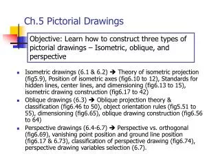
[Auto]CAD Basics: Foundations and 2D drawings
650 likes | 907 Vues
[Auto]CAD Basics: Foundations and 2D drawings. 7E300 International CA(A)D-course www.ds.arch.tue.nl/education/courses/CAD_International/. Overview. Introduction to CA(A)D-Packages: The promise The real world CA(A)D by Example: AutoCAD & ADT History System architecture Basic Geometry

[Auto]CAD Basics: Foundations and 2D drawings
E N D
Presentation Transcript
[Auto]CAD Basics: Foundations and 2D drawings 7E300 International CA(A)D-course www.ds.arch.tue.nl/education/courses/CAD_International/
Overview • Introduction to CA(A)D-Packages: • The promise • The real world • CA(A)D by Example: AutoCAD & ADT • History • System architecture • Basic Geometry • Coordinate systems • Basic transformations • Geometric primitives • Construction aids • Manual entry • Snaps • Alignments
Overview continued • Construction methods • Manipulation methods • Printing • Getting help
Overview continued 2nd lecture (Friday): • 3D geometry types • ‘Intelligent’ composite Objects • Architectural objects and helpers • Dimensioning • Printing • Rendering • Export
Goals • Give an overview of the topics involved • Give introduction to most basic modeling/drawing techniques • Give advise for self-study • Give introduction to AutoCAD/ADT
Building model paradigm • Building is designed assembling different objects • Every object of the building has a set of properties that can be interpreted in different contexts • Geometrical representations (i.e. drawings) are only one of many aspects. Drawings can be generated dynamically from existing data • Different domains (structural engineering, building physics etc.) have different views on building model
Building model paradigm • Advantages • ‘intelligent’ applications can gather all sorts of data (room sizes, material lists etc.) from a well defined model • Dependent drawings such as sections do not have to be redrawn on changes but automatically adapt
Building model paradigm • Problems • Additional (non-graphical) information has to be provided by architect • Coherency when changing objects • Object relations have to be designed • Complexity with all data required often cannot not be generated at design time
Future developments • Architect as ‘building programmer’? • Advanced input techniques • Virtual/Augmented reality • ‘Intelligent’ recognition handmade drawings • Voice recognition • Reuse of design strategies • Better compatibility through open standards (IFC etc.) • Finally: Paperless office at last?
Introduction to CA(A)D packages • The promises: • Let repetitive work be done by the machine • Draw more exactly • Draw quicker • Concentrate on the building instead of the drawing • Let drawings be generated from a n-dimensional building model • Get rid of paper by electronic documents • Accelerate cooperative work in the whole building cycle by reusing documents under domain-specific aspects • Let ‘intelligent’ functionality take care of easy tasks
Introduction to CA(A)D packages • The real world: • CA(A)D in most cases used as 2D pen and paper • Additional information required for building model seldom provided by architect • Document exchange critical due to lack of standards • Applications not error-prone • Functionality for architecture domain limited
CAAD applications in the architectural domain Marketshare CAAD-packages (Germany 2003) according to online survey on www.aecweb.de
CA(A)D by example: AutoCAD & ADT • History: • 1960 Ivan Sutherland SKETCHPAD • 1982 AutoCAD 1.0 introduced on COMDEX • 1985 AutoCAD 2.1 (R 6) goes 3D • 1986 AutoLISP • 1992 R 12 with new Solid kernel & rendering • 1993 R 12 goes Windows • 1997 R 14 most important version ever • 1998 ADT on R 14 • 2000 AutoCAD 2000
CA(A)D by example: AutoCAD & ADT • System Architecture (very simplified) End User ADT UI VisualizationOpenGL / D3D Standard AutoCAD UI API (C/C++, LISP, VB etc.) Geometry Kernel Operating System
Elemental Computer Graphics • Coordinate Systems • Almost all CAD-applications based on three-dimensional Cartesian system with right-hand orientation Image source: http://www.vard.org/mono/gait/soutas.htm Image source: http://en.wikipedia.org/wiki/Cartesian_coordinate_system
Elemental Computer Graphics • Coordinate Systems can be modified • Global: for the entire scene/’world’ (WCS in ACAD) • Local to an object / arbitrarily chosen by user (UCS in ACAD) Global (WCS) Local (UCS)
Elemental Computer Graphics • Units • Internal units and precision fixed and limited by machine and application • Real-world units (m, mm, ft, inches) can be applied arbitrarily suiting own needs • Be careful when exchanging data! • Choice of units affects dimensioning, text, hatches and line weights in ACAD! • Although units can be changed later, conversion problems esp. apply to switch between metric/imperial
Elemental Computer Graphics • Basic transformations • Translate (move) • Rotate • Scale
Basic geometry • Translation • Absolute: Set coordinates directly in current coordinate systemExample:Move absolute 5,1(ACAD: move:5,1)
Basic geometry • Translation • Relative: Set coordinates relative to current location in current coordinate systemExample: Translate relative5,1(ACAD move:@5,1)
Basic geometry • Rotation • Centered to object
Basic geometry • Rotation • Off-center rotation
Basic geometry • Scale • Uniform scaleExample: Factor 0.5 and 2
Basic geometry • Scale • Non-Uniform scale(Achieved by ‘Stretch’ command in ACAD or by scaling blocks)
Geometric primitives • Geometric primitives 2D • Point (Vertex) • Elemental type for all other geometry • Often used as construction aid
Geometric primitives • Line • Elemental type used to assemble other geometry types • Composed geometry (rectangle etc.) can be broken down to lines
Geometric primitives • Conic sections • Circles, arcs, ellipses, parabolas and hyperbolas are composed of conic sections • Granularity may be important for printing Image-source: Mathworld.Wolfram.com
Geometric primitives • Circle • May often be constructed in many different ways: • Radius • Diameter • 3 Points • 2 Tangents & radius • etc
Geometric primitives • Arc • Fraction of circle: • Can be used to construct complex curvedshapes by composition
Geometric primitives • Parametric curves: Bézier spline • Historically eldest of the free-form curves with some limitations • Control vertices, control polygon
Geometric primitives • Parametric curves: B-spline • Better control over curve • Found in many applications
Geometric primitives • Parametric curves: NURBS • Non Uniform Rational B-Spline • Used by Autocad, most flexible • X,Y,Z,W coordinates for control points
Geometric primitives • Pattern, hatches, fillings • Can only by applied to closed shapes (‘regions’ in ACAD, sort of 2D solids (more later on))
Geometric primitives • Pattern, hatches, fillings (continued) • Modern applications offer associative fillings
Basic operations • Copy • Creates one or more copies of a geometry or groups • Definition of base point can be used for proper placement
Basic operations • Array copy • Multiple copies in rectangular or polar (rotated) series
Basic operations • Mirror • Mirror using a mirror axis
Basic operations • Extend • Extend lines to arbitrary boundaries
Basic operations • Trim • Use arbitrary boundaries to cut away geometry
Basic operations • Break • Use two arbitrary boundaries to cut away geometry in-between
Basic operations • Stretch • Lengthen/shorten/scale/distort parts of geometries with some parts staying fixed
Coordinate entry ACAD • Directly enter coordinates into the WCS or current UCS by a comma-separated list with arbitrary precision • Examples for single points/vertices:1, 2.0, .3relative to last point: @1,2,3.01
Coordinate entry ACAD • Angular data entry:[Direction] < [Distance]Example: 5 units long line pointing to right in default WCS:90<5.0
Operation and selection • Order of operation in ACAD • Most command can either be invoked • Verb – object (state operation first and select objects to apply it to later on) • Object – verb (Select objects and state which operation to carry out) • The default method (if no other command explicitly invoked) in ACAD always is set to selection
Operation and selection • Selection in ACAD • Objects can be selected by • Pick single objects in succession (picking them again de-selects them • Drag rectangle from up-left to down right to select all objects inside rectangle • Drag rectangle form down-right to up-left to select those that are either inside or touched by selection rectangle
Operation and selection • ‘Transparent’ operations • While in the middle of a command sequence, the current command can be suspended for later finish in order to carry out in-between steps • Most typical examples are the different viewing command (zoom, pan, change perspective etc) • On the command line transparent mode of a command is activated by putting a ‘ in front of the command statement
Visual assistance • Ortho mode: only rectangular movements of mouse possible • Snapping: Catch i.e. one of the following points of existing geometry: • Endpoint • Midpoint • Center • Tangent • Perpendicular • Nearest (point on line/curve)
Visual assistance • OSnap tracking:Visual indication of graphic cursor such as • Parallel to existing line • Apparent intersection of two lines • Point on virtual extension of existing line • Grid: Virtual points in drawing space. When put into exclusive Grid-snap mode only these point can be chosen with the pointing device to construct geometry
Structuring drawings • Color / Line weight / Linetype • Historical method • Limited to specific set of colors in most applications • Might interfere with output needs • Colors not always distinguishable very well
Structuring drawings • Blocks / groups • Complete parts made easily available for reuse • Manipulate complex parts applying modifications only to on object