Chapter 5: Integumentary System
Chapter 5: Integumentary System. John F. Burke – surgeon who teamed with Professor Yannas in 1969 to work towards developing an artificial skin. . Ioannis V. Yannas (an Engineer) who along with Burke developed and pioneered the first use of Artificial Skin in surgery in 1981.


Chapter 5: Integumentary System
E N D
Presentation Transcript
Chapter 5: Integumentary System
John F. Burke – surgeon who teamed with Professor Yannas in 1969 to work towards developing an artificial skin.
Ioannis V. Yannas (an Engineer) who along with Burke developed and pioneered the first use of Artificial Skin in surgery in 1981.
Figure 5.1 Skin structure. Hair shaft Dermal papillae Subpapillary vascular plexus Epidermis Papillary layer Pore Appendages of skin Dermis • Eccrine sweat gland Reticular layer • Arrector pili muscle • Sebaceous (oil) gland Hypodermis (superficial fascia) • Hair follicle Nervous structures • Hair root • Sensory nerve fiber Cutaneous vascular plexus • Pacinian corpuscle Adipose tissue • Hair follicle receptor (root hair plexus)
Figure 5.2 The main structural features of the skin epidermis. Keratinocytes Stratum corneum Most superficial layer; 20–30 layers of dead cells represented only by flat membranous sacs filled with keratin. Glycolipids in extracellular space. Stratum granulosum Three to five layers of flattened cells, organelles deteriorating; cytoplasm full of lamellated gran- ules (release lipids) and keratohyaline granules. Epidermal dendritic cell Stratum spinosum Several layers of keratinocytes unified by desmosomes. Cells contain thick bundles of intermediate filaments made of pre-keratin. Tactile (Merkel) cell Stratum basale Deepest epidermal layer; one row of actively mitotic stem cells; some newly formed cells become part of the more superficial layers. See occasional melanocytes and epidermal dendritic cells. Dermis Sensory nerve ending Melanocyte Desmosomes (a) Dermis (b) Melanin granule
Figure 5.3 The two regions of the dermis. Dermis (b) Papillary layer of dermis, SEM (22,700x) • Light micrograph of thick • skin identifying the extent of • the dermis, (50x) (c) Reticular layer of dermis, SEM (38,500x)
Figure 5.3a The two regions of the dermis. Dermis • Light micrograph of thick skin identifying • the extent of the dermis, (50x)
Figure 5.4 Dermal modifications result in characteristic skin markings. Frictionridges Openings of sweat gland ducts (a) (b)
Figure 5.5 Cutaneous glands. Sweat pore Sebaceous gland Dermal connective tissue Eccrine gland Sebaceous gland duct Hair in hair follicle Duct Dermal connective tissue Secretory cells (a) Photomicrograph of a sectioned sebaceous gland (220x) (b) Photomicrograph of a sectioned eccrine gland (220x)
Figure 5.6a Structure of a hair and hair follicle. Follicle wall • Connective tissue root sheath • Glassy membrane • External epithelial root sheath • Internal epithelial root sheath Hair shaft Hair • Cuticle • Cortex • Medulla Arrector pili (a) Diagram of a cross section of a hair within its follicle Sebaceous gland Hair root Hair bulb
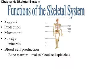
Figure 5.7 Structure of a nail. Lateral nail fold Lunule (a) Free edge of nail Body of nail Eponychium (cuticle) Proximal nail fold Nail bed Root of nail Nail matrix (b) Hyponychium Phalanx (bone of fingertip)
One example of how to represent Melanin Inheritance patterns via a modification of the Punnet Square.
1 m 106 nm 106 nm 10–5 nm 1 nm 10–3 nm 103 nm 103 m Micro- waves Radio waves Gamma rays X-rays UV Infrared Visible light 380 450 500 550 600 650 700 750 nm Shorter wavelength Longer wavelength Lower energy Higher energy The electromagnetic spectrum
400 500 700 600 Which wavelengths of light are most effective in driving photosynthesis? This graph shows the absorption frequencies of two chlorophylls and carotenoids. Chlorophyll a Chlorophyll b Absorption of light by chloroplast pigments Carotenoids Wavelength of light (nm)
Absorption spectra for melanin (in German)
Figure 5.9 Estimating the extent and severity of burns using the rule of nines. Totals 1 4 / % 2 Anterior and posterior head and neck, 9% Anterior and posterior upper limbs, 18% Anterior trunk, 18% 1 1 Anterior and posterior trunk, 36% 4 / % 4 / % 2 2 9% 9% (Perineum, 1%) Anterior and posterior lower limbs, 36% 100%
Figure 5.10 Partial thickness and full thickness burns. 1st degree burn 3rd degree burn 2nd degree burn (b) Skin bearing full thickness burn (3rd degree burn) (a) Skin bearing partial thickness burn (1st and 2nd degree burns)