Chapter 5 Air-Conditioning Components
Chapter 5 Air-Conditioning Components. Metering Devices, Storage Components, and Evaporator. Possible Metering Components. Internally Equalized Thermal Expansion Valve Externally Equalized Thermal Expansion Valve H-Block (Valve) Fixed Orifice Tube. Main Purpose of TXV. Throttling:

Chapter 5 Air-Conditioning Components
E N D
Presentation Transcript
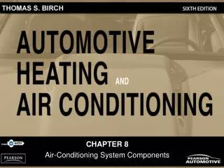
Chapter 5 Air-Conditioning Components Metering Devices, Storage Components, and Evaporator
Possible Metering Components • Internally Equalized Thermal Expansion Valve • Externally Equalized Thermal Expansion Valve • H-Block (Valve) • Fixed Orifice Tube
Main Purpose of TXV • Throttling: • Division between high and low • Restricts flow to drop psi so refrigerant can boil • Modulation: • Sends proper amount through evaporator • Control: • Flooded evaporator- to much refrigerant and liquid can pass out to the compressor • Starved- not enough to remove heat.
Internally Equalized TXV • Remote bulb connected to the capillary tube • Bulb wrapped tight to the outlet side of the evaporator • As the temperature of the bulb raises the, gas/liquid inside, pressure raises, forcing on the top of the diaphragm, causing the valve to open. • As this happens, evaporator pressure rises, in turn causing the valve to close slightly. (equilibrium) • As more refrigerant goes through the evaporator it causes the outlet side temperature to decrease, which causes the valve to close.
Internally Equalized TXV Cont. • Operation controlled by three separate pressures • Sensing bulb, applied to the top of the diaphragm • Evaporator inlet, applied to opposite side of the diaphragm (tries to close the valve) • Spring, applied to the needle assembly and diaphragm ( to close)
Internally Equalized TXV Refrigerant Flow Don’t kink tube!
Externally Equalized TXV • Differences: • No drilled passage to allow displacement from the inlet side of the evaporator • Equalizer tube attached to outlet side of the evaporator for diaphragm displacement • Advantage • Externally equalized valve overcomes the effect of refrigerant pressure drop on systems with large evaporators.
Operation of the H-block • Two passages: • Condenser (r/drier) to the Evaporator • contains the ball and spring metering orifice • Controls the amount of refrigerant that goes into the evaporator • Evaporator to the Compressor • Temperature sensing element (diaphragm) • As the temp. of the gas from the evaporator increases it causes the ball and spring to move allowing more refr. to enter the evaporator causing the temp to decrease
FOT • Located in the liquid line between the outlet of the condenser and the inlet of the evaporator • Calibrated restriction • Division between the high and low sides that meters the refrigerant into the evaporator • High psi, high temp liquid enters the tube and low psi, lower temp liquid exits to the evaporator.
Refrigerant Flow • Depends on: • Size of the orifice (does not change) • Amount of subcooling that has been allowed • Orifice tube inlet and outlet side pressure differences • Color coding determines orifice size • .067” to .047” range orifice
Variable Orifice Valve (VOV) Uses system pressure to move a spring loaded metering piston -aftermarket part that will work in many systems
Advantages of VOV • Cabin air that is 5-12 F less warm • Improved performance when converting to 134a • Reduced compressor load • Extended life • Better fuel economy • Less emissions
Superheat • To prevent liquid from entering the compressor, the metering device allows the right amount of refrigerant to enter the evaporator. This is so the refrigerant will all evaporate far enough back in the evaporator so the vapor will be 8-12 degrees superheated before it exits.
Measuring Superheat • To determine the superheat setting of a valve: • Measure the evaporator outlet temp. and psi • Using the following chart look at the pressure and determine the temperature • The temperature found on the chart is the saturation point (boiling point) of the refrigerant at the current pressure • Now subtract that temperature from the actual temperature at the evaporator outlet= superheat
Pressure Chart for R-134a40psi low side, 45 degrees chart, 55 degrees actual=?
Why Superheat? • Superheat prevents the refrigerant from turning back to a liquid on the way to the compressor even if the temperature drops slightly.
Tube and Fin Type Evaporator(Temperature change only after changing state)
Plate and Fin Type Can not flush
Evaporator • Removes heat from the cabin due to the BTUs required to boil the refrigerant to a gas • The blower fan draws warm cabin air through the fins and the effect is cooler air coming out • Construction determines capacity: • Size of the evaporator • Number of fins (surface area) • Fan capacity
Evaporator Cont. • Must be large enough in relation to the amount of refrigerant the metering device passes on so that all refrigerant changes states • Flooded evaporator • Too much refrigerant, can not all be boiled • Starved evaporator • Not enough refrigerant to remove heat • Fins can be straitened other non-repairable
Accumulator on Firewall Located in a warm place.
Accumulator • Only used on systems that use an orifice tube • Located between the evaporator and the compressor • Prevents liquid from returning to the compressor • Stores excess liquid and absorbs moisture • With out a way to change the amount of refrigerant that enters the evaporator it can run Flooded
Summary • A properly balanced air conditioning system, that has no external leaks, and the proper amount of oil, should require very little maintenance. • Anytime one or more of these conditions change, failures can occur. • Depending on the working conditions of the systems (high humidity, dirt) service intervals may have to be adjusted.