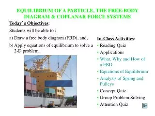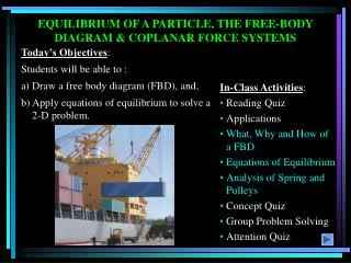
EQUILIBRIUM OF NON-CONCURRENT COPLANAR FORCE SYSTEM
560 likes | 1.5k Vues
EQUILIBRIUM OF NON-CONCURRENT COPLANAR FORCE SYSTEM. When a body is in equilibrium, it has neither translatory nor rotatory motion in any direction. Thus the resultant force R and the resultant couple M are both zero, and we have the equilibrium equations for two dimensional force system

EQUILIBRIUM OF NON-CONCURRENT COPLANAR FORCE SYSTEM
E N D
Presentation Transcript
EQUILIBRIUM OF NON-CONCURRENT COPLANAR FORCE SYSTEM When a body is in equilibrium, it has neither translatory nor rotatory motion in any direction. Thus the resultant force R and the resultant couple M are both zero, and we have the equilibrium equations for two dimensional force system Fx = 0; Fy = 0 Eq(1) M = 0 These requirements are both necessary and sufficient conditions for equilibrium. Back
Supports: A structure is subjected to external forces and transfers these forces through the supports on to the foundation. Therefore the support reactions and the external forces together keep the structure in equilibrium. Types of supports There are different types of supports. Some of them are a) Roller Support b) Hinged or pinned support c) Fixed or built in support Some supports are shown in the figure along with the reactions that can be mobilised.
Action on body Types of Supports (a) Flexible cable ,belt ,chain, rope BODY BODY T Force exerted by cable is always a tension away from the body in the direction of cable Contact forces are normal to the surfaces (b) Smooth surfaces F F
(c) Roller support Contact force is normal to the surface on which the roller moves. The reaction will always be perpendicular to the plane of the roller . Roller support will offer only one independent reaction component.(Whose direction is known.)
( d )pinned Support / hinged support Rh θ Rv R This support does not allow any translatory movement of the rigid body. There will be two independent reaction components at the support. The resultant reaction can be resolved into two mutually perpendicular components. Or it can be shown as resultant reaction inclined at an angle with respect to a reference direction.
(e) Fixed or Built-in Support M RH Rv M
(contd .) This type of support not only prevents the translatory movement of the rigid body, but also the rotation of the rigid body. Hence there will be 3 independent reaction components of forces. Hence there will be 3 unknown components of forces, two mutually perpendicular reactive force component and a reactive moment as shown in the figure.
TYPES OF BEAMS A member which is subjected to predominantly transverse loads and supported in such a way that rigid body motion is prevented is known as beam. It is classified based on the support conditions. A beam generally supported by a hinge or roller at the ends having one span(distance between the support) is called as simply supported beam. A beam which is fixed at one end and free at another end is called as a cantilever beam. A B HA MA VA span span (b) Cantileverbeam (a) Simply supported beam
If one end or both ends of the beam project beyond the support it is known as overhanging beam. A cantilever with a simple support anywhere along its length is a propped cantilever. A B HA MA VA span (c) Overhanging beam (right overhang) (d) Propped Cantileverbeam
A beam which is fixed at both ends is called a fixed beam. A beam with more than one span is called continuous beam. HA HA HB MB MA span VC VB VB VA VA (f) Two Span continuous beam (e) Fixed beam
Statically determinate beam and statically indeterminate beam: Using the equations of equilibrium given in Eq(1) ,if all the reaction components can be found out, then the beam is a statically determinate beam ,and if all the reaction components can not be found out using equations of equilibrium only, then the beam is a statically indeterminate beam. In the above fig (a),(b)and (c) are statically determinate beams, where as (d),(e) and (f) are statically Indeterminate beams.
If the number of reaction components is more than the number of non-trivial equilibrium equations available then such a beam is a statically indeterminate beam. If the number of reaction components is equal to the number of non-trivial equilibrium equations available then such a beam is a statically determinate beam If the number of reaction components is less than the number of non-trivial equilibrium equations available then such a beam is an unstable beam.
Determination of Beam reactions Since three equilibrium equations are available, for a planar structure a maximum of three unknown independent reaction components can be determined using these equations. Step I: Draw the free body diagram of the structure showing the given loadings and the reactions at the supports. Step 2: Apply the equations Fx = 0, Fy = 0, M = 0. Assuming some directions and senses for unknown forces and moments. Step 3: solve for unknown reactions. If any of them is positive, it is along the sense initially assumed while drawing the FBD. If it is negative, it is opposite to the initially assumed sense
Problems (1) A beam AB of span 12m shown in the figure is hinged at A and is on rollers at B. Determine the reactions at A and B for the loading shown. 20kN 25kN 30kN 30 45 A B 4m 3m 3m 2m
20kN 25kN 30kN 45 FBD 30 HA B VA VB 3m 3m 4m 2m Problems Solution • Fx = 0 HA – 25cos 30 – 30cos45 = 0 • Fy = 0 VA – 20 – 25 sin30 – 30sin45 +VB = 0 • MA = 0 -20×4 - 25 sin30×7 - 30 sin 45×10+ VB ×12=0
Problems Solution(contd.) HA=42.86kN, VA=22.07kN, VB=31.64kN HA RA VA RA= 48.21 kN = 27.25
(2) Find the Support reactions for the given beam loaded as shown in the figure. 60kN 40kN/m 0.5m B A 2m 1 m 60° 5m
Solution Solution 40kN/m 60kN HA A RBH=RBCos30 B C 30kNm VA FBD 60° RB 1m 2m 2m RBv = RBCos60 Fx = 0 HA + 60 – RB Cos30 = 0 Fy = 0 VA + RB Cos60 – 40 x 2 = 0 MA = 0 -30 - 40×2×4 + RB Cos60×5 = 0 HA [Ans: RB=140kN VA=10 HA=61.24 RA= 62.05kN = 9.3] RA VA
(3) Find the Support reactions for the given beam loaded as shown in the figure. 0.5m 30kN 80kN/m 100kN A B 3m 2m 1m
Solutions 30kN 80kN/m 15kNm A 100kN HA B VA 3m 2m 1m VB FBD
120kN 30kN FBD 1m 15kNm 100kN HA A C B 2m VB VA 6 m Fx = 0 HA + 100 = 0 Fy = 0 VA + VB – 30 –120 = 0 MA = 0 - 30×2 - 15 - (120)x5 + VBx6 = 0 [ Ans: VB= 112.5kN VA =37.5kN HA= – 100kN RA= 106.8kN = 20.56] HA RA VA
(4) Find the Support reactions for the beam loaded as shown in the figure. 23kN 20kN 15kN/m 30kN 3m 2m 2m
; Solution 45kN 23kN 20kN 30KN A HA MA FBD 1.5m 1.5m 2m 2m VA Fx = 0 HA = 0 Fy = 0 VA –45 –30 –23 –20 = 0 MA = 0 MA –45x1.5 –30x3 –23x5 –20x7=0 [ Ans: VA = 118kN MA =412.5kNm]
(5) Find reactions at A,B,C and D 20KN/m 10KN/m D A B C 2m 3m 1m 2m
Solution 10kN/m 10kN/m 10kN/m D C 3m 1m 2m Rc A B 2m 3m 1m 2m
40kN Solution FBD of top beam 20kN C D 2.0m 1.33m 2m Rc 0.67m VD A B FBD of bottom beam VB C VA 2m 3m
40kN Solution 20kN 2m 3.33m RC 0.67 VD For top Beam : Fy = 0 Rc –40 –20+VD=0 MD = 0 -Rc × 6 +40 × 4 +20 × 3.33=0 Solving the above eqns RC=37.77kN; VD=22.23kN
(Contd.) For bottom beam : Fy = 0 VA –37.77–VB=0 MB = 0 -VA× 5 +37.77 ×3=0 Solving the above eqns VA=22.66kN; VB=15.10kN RC=37.77kN 2m VA 3m VB
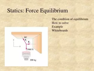
(6) A ladder of length 5m has a weight of 200N. The foot of the ladder rests on the floor and the top of it leans against the vertical wall. Both the wall and floor are smooth. The ladder is inclined at 60 with the floor. A weight of 300N is suspended at the top of the ladder. Find the value of the horizontal force to be applied at the foot of the ladder to keep it in equilibrium.
Solution 300N HB 2.5m 200N FBD OF LADDER 2.5m 600 HA VA
Solution Fy = 0 VA – 200 – 300=0 ::VA=500N MA = 0 HB x 5 sin60 – 200 ×2.5 cos 60 – 300 ×5cos60=0 :: HB=230.94N Fx = 0 HA –HB=0 HA=230.94N(Ans.) 300N 2.5m HB 200N 2.5m 600 HA VA
(7) Find the reactions at the supports A and C of the bent B C 20 kN/m 3m A 2m
Solution B C Y VC 20 kN/m 3m X FBD HA VA 2m
Solution (contd.) • Fx = 0 60–HA=0 • Fy = 0 VA+VC=0 • MA = 0 VCx2-60 ×1.5=0 B C 3m VC 60kN FBD HA VA 2m
Solving the above Ans: VA = - 45kN VC = 45 kN HA = 60kN B C RA=75 kN VC 60kN 36.90 FBD after finding reactns # ve sign for VA indicates ,reaction is downwards and not upwards as assumed initially. HA VA
C B A 1m 4m 30° D (8) A roller (B) of weight 2000N rests as shown in the fig. on beam CD of weight 500N.Determine the reactions at C and D. Neglect the weight of beam AB.
Solution: 2000N RAB FBD of Roller RB Hc 300 Vc 500N 1m FBD of beam CD 1.5m 30° 2.5m D VD
Solution: 2000N RAB FBD of Roller RBCD 300 FBD of Roller : Fy = 0 RBCD cos 300 –2000=0 Fx = 0 RAB – RBCD sin 300 =0 Solving above eqns : RBCD=2309.4N; RAB=1154.7N
For bottom beam : Fy = 0 VD –500+Vc –2309.4cos30=0 MC = 0 -VD× 5cos30 +500 × 2.5 × cos30-2309.4 × 1=0 Solving the above eqns: VD=783.33N; VC=1716.67N Fx = 0 2309.4 sin 30 –HC =0 Hc=1154.7 N 2309.4N 300 Hc Vc 500N 1m 1.5m FBD of beam CD 30° D 2.5m VD
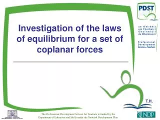
(9) Compute the reactions for the bent beam shown in the figure at A and F. 300Nm 50 N/m B C D A 45° F 4m 3m 3m 4m
Solution MF = 0 – VA × 14 +200 × 5 – 300=0 VA=50N FX=0 HF=0 FY=0 VA +VF=200; VF=200 – 50=150N 200 N 2m 300Nm B D C 45° A HF F VA 3m 4m 4m 3m VF FBD 18kN 26.570 RA=20.12kN 9kN
(10) Determine the support reactions for the trees shown A 3KN 3KN G 4m 3KN F E B C D 4m 4m 4m
Solution A 3KN FBD HA 3KN G VA 4m 3KN F B HB E C D 4m 4m 4m
18kN 26.570 9kN RA=20.12kN MA = 0 HB × 4 – 3 × 4 – 3 × 8 – 3 × 12=0 HB=18kN FX=0 : –HA+HB=0 HA=18kN FY=0 VA –3 –3 –3=0; VA=9kN 3KN A 3KN HA 3KN VA 4m HB 4m 4m 4m
Problems for practice (1)Find the reactions at A,B,C and D for the beam loaded as shown in the figure(Ans.RA=RB =34kN;RC=28.84kN; MC=-140kNm ; θC=-33.69 ˚ ) 12kN/m 20 kN 12kN/m 4kN/m 4kN/m 30kN 3 A 4 B C 40kNm 1m 2m 1m 1m 2m 1m 1m 2m
(2)A uniform bar AB of weight 50N shown in the figure supports a load of 200N at its end. Determine the tension developed in the string and the force supported by the pin at B.(Ans.T=529.12N;RB=807.15N, θB=64.6˚) string 2.5m B 60˚ A 200N 2.5m 2.5m
(3)Find the position of the hinged support (x),such that the reactions developed at the supports of the beam are equal.. (Ans.x=2m.) 15kN 18kN/m 10kN/m x 1.4m 1.0m 3.0m 2.0m 0.6
(4)A right angled bar ABC hinged at A as shown in fig carries two loads W and 2W applied at B &C .Neglecting self weight of the bar find the angle made by AB with vertical(Ans:θ =18.44˚) A L m θ B W C 0.5L 2W