CONCURRENT FORCES & FORCE DIAGRAMS
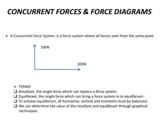
CONCURRENT FORCES & FORCE DIAGRAMS. A Concurrent F orce System, is a force system where all forces start from the same point. 100N. 2 00N. TERMS: Resultant, the single force which can replace a force system. Equilibrant, the single force which can bring a force system in to equilibrium.

CONCURRENT FORCES & FORCE DIAGRAMS
E N D
Presentation Transcript
CONCURRENT FORCES & FORCE DIAGRAMS • A Concurrent Force System, is a force system where all forces start from the same point. 100N 200N • TERMS: • Resultant, the single force which can replace a force system. • Equilibrant, the single force which can bring a force system in to equilibrium. • To achieve equilibrium, all horizontal, vertical and moments must be balanced. • We can determine the value of the resultant and equilibrant through graphical • techniques.
CONCURRENT FORCES & FORCE DIAGRAMS Lets consider the previous force system. 100N Select a scale to draw the forces against. In this case, lets say 5mm = 10N. Draw the 200N force to scale, i.e. 100mm. Draw the 100N force from the end of this vertically upwards. i.e. 50mm. 4. Join the ends and measure this line. 200N Line length = Approx. 110mm So resultant = (110/5) x 10N = Approx. 220N Resultant 50mm 100mm
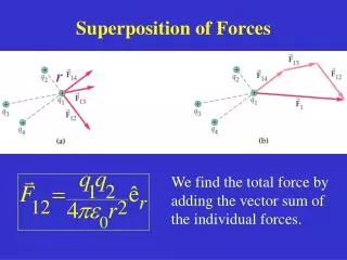
CONCURRENT FORCES & FORCE DIAGRAMS The Equlibrant will always be in the opposite direction, but will always have the same value. This technique works for force systems with more than 2 forces, as an example. F3 F2 F1 F4 F4 F3 Force System F2 R F1
CONCURRENT FORCES & FORCE DIAGRAMS Pupil problems: 100N @30 1) 50N @ 45 2) 65N 100N 30N 60N @ 45 50N @45 150N 200N 75N 3) 50N
STRESS & STRAIN STRESS = Load/Cross Sectional Area (Nmm-2) Strain = Change in Length/ Original Length (no units) Example 1: A structural member is subjected to a compressive force of 20000N. If the diameter of the member is 250mm, calculate the stress within the member. If the load reduces the member length by 0.5mm and the original length was 2m, calculate the strain.
Solutions Stress = 3.14 x 125 x 125 = 49062.5 mm2 Stress = Load/Cross Sectional Area = 20000/49062.5 = 0.407Nmm-2 Strain Strain = Change in Length/ Original Length = 0.5/2000 = 0.00025