Chapter 2 Embedded Software Design and Development
Chapter 2 Embedded Software Design and Development. Objectives Introduce State Chart in embedded software analysis and design Introduce time requirement analysis for real-time systems Discuss the Multi-tasking Design and RTOS . 2.1 Overview.

Chapter 2 Embedded Software Design and Development
E N D
Presentation Transcript
Chapter 2 Embedded Software Design and Development Objectives Introduce State Chart in embedded software analysis and design Introduce time requirement analysis for real-time systems Discuss the Multi-tasking Design and RTOS
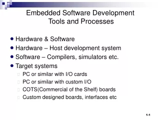
2.1 Overview • The embedded system Software Development Life Cycle (SDLC) with its special consideration in the resource constrains including CPU, time, memory, operating system, multi-tasking concurrency, time-to-market, reliability, and other non-functional attribute constraints special software engineering methodology is needed for the software design and development. • Because the embedded software is not deployed on a general-purpose computer system, the embedded software in C/C++ or other high level programming languages must be developed and tested on a cross-platform machine such as PC, and then be loaded to a target microcontroller memory to be tested
Contd. • For a successful embedded system development, embedded system hardware and software co-design based on the system specification is also very necessary to get the prototype smoothly. • In co-design phase, software analyst/designer need to work with hardware team members to decide on the type of microcontrollers and microprocessors according to the requirement of the speed and memory, power consumption, the number of I/O devices such as ADC, cost per unit, size and packaging, and others.
Also, software development tools must be selected and the partition between software and hardware implementation should be decided in co-design phase: decision on time delay implementation by software program or with a hardware timer. • The SDLC proceeds in phases consisting of system specification, analysis, design, coding, and testing. The dash-lines indicate the required iteration processes when the changes
The requirement specification provides an • unambiguous description of system functionality and • no-functional attribute requirements. It is the basis of • initial modeling and design processes. • The modeling process analyzes the requirement • specification and presents an abstraction model • describing the embedded software structure and • behaviors of a large complex embedded software. • Software design process/phase provides a blueprint for development implementation which divides the whole system into subsystem partitions and specifies the relationships between the subsystems. • Both modeling process and design process are independent from coding in term of programming methodology and language implementation
2.2 Software Requirement Specification Due to various constraints in resources and performance all the quality attributes should be identified in the requirement analysis process. Quality attributes can be categorized into three groups: • Implementation attributes (not observable at runtime) • Runtime attributes (observable at runtime) • Business attributes
2.2.1. Implementation attributes(not observable at runtime) • Resource availability: This refers to memory space, power supplier, CPU frequency, and RTOS. • Maintainability & extensibility: This refers to the ability to modify and extend conveniently. • Testability: system facilitates the establishment of test cases. A complete set of test case documentation with system design and implementation. • Flexibility: Ease modification of a system to cater to different environment or problems for which the system is originally not designed.
2.2.2. Runtime attributes (observable at runtime) • Availability: the ability of a system to be available 24x7. Availability can be achieved via replication and careful design to cope with failures of hardware, software, or the network • Security: the ability to cope with malicious attacks from outside or inside of the system. Security can be improved by installing firewalls and establishing authentication and authorization processes, and using encryption. • Performance: The efficiency such as response time, throughput, resource utilization • Usability: “satisfaction” from a human perspective in using the system. Usability includes completeness, correctness, compatibility, and user friendliness - friendly user interface, complete documentation, and help support. • Reliability: the failure frequency, the accuracy of output results, the mean-time-to-failure (MTTF), the ability to recover from failure, and the failure predictability
2.2.3. Business attributes • Time to market: The time it takes from requirement analysis to the date product is released. • Cost: expense of building, maintaining, and operating the system. • Lifetime: the period of time that the product is “alive” before retirement.
2.3 Embedded Software Modeling Analysis and Design • The analysis process starts with the system context analysis by Context Diagram , system key tasks, and their relationship identification. • The focus - the reactive behaviors of the embedded software including: periodic or aperiodic events, parallel or serial data processing, synchronous or asynchronous communication, real-time or soft-time in response reaction, and others. • The context diagram is derived from the requirement specification. It provides a preliminary draft of the embedded software and its environment which shows all events the system interacts with. It specifies elements of a system, data and data flow around the system, and the system internal and external communication
Sample • Here is a multiple room temperature control system specification. The system provides centralized and distributed temperature control functions. A local desired temperature can be set by a room control panel in each individual room or a global temperature can be set at the central control panel. • The temperature sensors are installed in each room to monitor the current room temperature. The A/C and furnace are turned on or off by the controller depending on the desired temperature and the current temperature.
Contd. • Each room has a vent driven by a motor to control the air flow so that different room may reach different desired temperature HVDC system
A context diagram consists of the controller module, keypad module, sensor module, LCD module, vent motor control module, A/C unit control module, furnace control module, etc. It depicts the input events the controlled actuators. At this stage, also understand the system requirement (functional and non functional) select microcontroller, mode of communication (serial or parallel) with devices, adoption of RTOS
Finite State Machine (FSM) and StateChart • The system modeling presents an abstraction of system (a high level description) in software aspects • It helps to understand the functional requirement in block diagram, identify all required software elements and tasks, model the behaviors of embedded system software • The stateChart diagram is a very popular analysis modeling method for real time embedded software which is derived from Finite State Machine (FSM).
State A FSM consists of a finite number of states, transitions between the states, and actions to be performed. A state represents a certain behavior in a period of time in performing tasks or being idle waiting for events . In the state notation you can specify the entrance actions, state actions, and exit actions
Transition • A transition indicates a state change guided by condition or events. • A transition is a response to an event with a set of attributes that moves the system from one state to another state. There may be many transition links from one state to other states with different events or with same event but different guide conditions. • A event can refer to either internal event (such as timer timeout overflow) or external event (a car detected by sensor), • a condition can refer to a set of variable values • a reaction can refer to reassignment of these variables or new event creation.
When the test strip is inserted into the monitor the system moves to a ready state waiting for the blood sample and the system moves back to the idle state when the strip is removed. At this time patient can set the strip code in two digits and it is saved in the data store. If the blood is not enough an error message is displayed in the display state and system goes back to the ready state to wait for new blood sample. If the blood sample is valid it moves to the computation state to analyze the glucose level with the code reference
FSM Implementation init state S0; while(1) { switch(state) { S0: action0; if (cond1) state = S1; else (cond2) state = . . .; break; S1: action1; if (cond3) state= . . . ; else if (cond4) state = . . . ; else state = S0; break; S2: action2; If (...) ... } }
Contd. • However, a FSM can’t represent multiple states active simultaneously and it can’t describe any nested states within states in a hierarchical structure neither. It can only be used for simple system with few states. • A simple flat FSM for a counter or validation task, where s1-s4 take inputs and validate input, if the input are not valid then the system moves to state S5 to handle exception, and then goes back to initial state to start over again. • It will be too complicated if the number of states goes large.
We can group these state to make a nested state S’ (set of sub-states) so that the transition between S’ and S is greatly simplified each state is simple enough to have its sole responsibility. Nested StateChart
the init state (AC-off), final state, and AC-On state in a stateChart diagram.
Two tasks can be running concurrently with links between these them. The dash links indicate the synchronization and message pass communication between tasks such that one task can notify another task by a signal of job completion or other events. There may also be an external event notification such as interrupt request from any external event resource.
Hierarchy and Concurrency in StateChart complicated logical relationships can be represented by the combinations of logic AND (concurrency) and logic OR (selection) in a stateChart. The following diagram exhibits the concurrency behavior and hierarchy structure
The state A is a super state of the state B and state C while both states of B and C are nested in state A. • The concurrency of B and C are separated by a vertical bar • The state D and E inside C are two parallel states in state B • The logical relation between the pair of B and C and the pair of D and E is a logical AND which indicates B and C will be active at same time after state A is entered which is the same as the states D and E after B • Once state C is entered, the default state is F and state F and state G will be active alternatively so that the relation between F and G are logical OR. only one of these two states can be active at same time. • The tree on the right side shows the logical relationship in term of concurrency between sibling states and alternate relationship between super-sub states.
History State • A concurrent state can contain one history state and one deep history state. • A transition to the history state will resumes the state it last had in this state region. A typical application of the history state is for the Interrupt Service Routine(ISR) return, which returns the control to where it left. • A history state can have multiple incoming events/actions. It can have at most one outgoing events/actions, which points to the “resume” state if the transition occurs for the first time without any history. The regular history state only applies to the level in which it appears while the deep history state entrance applies to the most recently visited state in the deepest level. • It is noted as H*.
After completion of interrupts the control will return to where it left as noted by the H states. E.g., a timer can trigger a timeout event which interrupts a task, then an ISR handle the event, and the interrupted task resumes afterwards.
Summary of stateChart • The FSM is good fit for control oriented system analysis which monitors inputs, controls the transitions by stimulus/events, and takes actions on the states. • The stateChart is multi-tasking oriented which can support multiple state machines, communication, and synchronization, support the real time multi-tasking software analysis modeling. • The stateChart consists of states (including initial and final states), signals(events), transitions with triggers( event and data conditions), and actions (e.g., emitting signals). It also supports state hierarchy, i.e., nested states, and communication between active states. • Assign a concurrent task (a concurrent state) for each important device control to divide the whole software design into multiple partitions. • Well known statechart simulation development tools available in market, StateMate, SpeedChart, StateFlow, BetterState, VisualVHDL, StateVision, and LabView. Some tools such as Rational Rose, Rhapsody can even convert the stateChart into actual code in C or VHDL. • Statechart provides a formal model for reactive dynamic behavior of embedded system especially for the concurrency behavior.
2.4 Time Requirement Analysis for Real-Time Systems • Most embedded software are real-time systems, some waiting tasks are guaranteed to be given the CPU when an external event occurs. Real time systems are designed to control devices such as industrial robots, which require timely processing. • Such system must meet timing requirements regardless hard real-time embedded system or soft real-time embedded systems. Almost all embedded software are multitask oriented in which multiple tasks, also known as process, share common processing resources such as a CPU.
With a single CPU, only one task is said to be running at any point in time, meaning that the CPU is actively executing instructions for that task while all others are waiting. • The act of reassigning a CPU from one task to another one is called a context switch. Running multiple tasks concurrently can make maximum use of CPU time, reduce the CPU idle time to a minimum degree, and the urgent requests can be handled immediately.. • Threads are lightweight processes which share entire memory space. Thus, threads are basically processes that run in the same memory context. Context switch between threads does not involve changing the memory context. • A task can even have multiple threads. The term task represents both process and thread. The multi-tasking design and implementation can separate the design concerns, divide and conquer the problem domains easier but interaction and resource sharing between tasks still bring many design and implementation complexities.
Each task must keep tracks on its own concern and has its own state including its own status: CPU register status, program count, its own memory space and stack, so that CPU can switch back and forth between these processes/tasks. • When an event request occurs in a reactive embedded system the target task must respond the event within a period time. The Worst-Case Execution Time (WCET) of a task tells the maximum length of time the task could take to execute. The actual response time may be shorter than the WCET. It is of prime importance for the timing analysis of hard real time system. • There is also a deadline for each task to complete for either periodic events or aperiodic events.
Let us exam the multi-tasking 8051 RTX-51. It recognizes four task states; a process is always in one of these states at any time: 1. READY Tasks which are READY to run CPU are in this state. 2. RUNNING (ACTIVE) Task which is currently being executed by CPU processor. Only one task can be in this state at any time. 3. BLOCKED (WAITING) Task waits for an event or resource. 4. SLEEPING Tasks before ready or after running are in this state.
In the life cycle of a task in a multitasking environment, a task moves from one state to another state and compete CPU with other state. The task selection for CPU (running state) is determined by a scheduler (also called dispatcher). 1. The task with the highest priority of all tasks in the READY state is executed. 2. If several tasks of the same priority are in the READY state, the task that has been ready the longest will be the next to execute. 3. Task switch is only executed if the first rule would have been otherwise violated (exception: round-robin scheduling).
Non-Preemptive Scheduling • Non-preemptive multitasking is a simple task scheduling for periodic time requirement system. Once a task started it will hold CPU until it completes • Cooperative multitasking • tasks can self-interrupt and voluntarily give control to other tasks. the process currently controlling the CPU must be able to offer control to other processes. All tasks must work cooperatively and it does not need any context switch from a running task to another task. • The context switch takes a lot of time to save its current status including its stack and Program Count(PC) address so that it can resume its task after it comes back to run the CPU.
Contd. • A simplified modeling for a non-preemptive scheduling can be a cyclic scheduling that the tasks can be scheduled in a fixed static table off-line. • Assume that the embedded software consists a set of tasks and all of them have their fixed period. Aperiodic events can be estimated by their worst case interval gap between two consecutive task events. • Also, assume that all tasks are independent and WCET are known in advance so that the deadline is at the end of WCET.
Contd. You can also schedule the higher priority task before the tasks with lower priority. The advantage of such cyclic scheduling: simple, zero overhead of context switch between process/task; The disadvantage: inflexibility. If there are n tasks and the WCET of ith task is ci, thenthe period of any task Ti must satisfy Ti >= ∑ cj (j = 1,2, …, n) Otherwise some task will miss its deadline.
software analyst and design should make each task as shorter as possible. For these long tasks you may need to break it into many small pieces. • Here is a cyclic schedule example: You can find that the period of T1 (50ms) > c1(20ms) + c2(25ms). 100 50
The template for the non-preemptive cyclic scheduling implementation. Assume there is a timer set on the period of 50 ms. while(1) { Wait_for_50ms_timer_interrupt; do task1; Wait_for_50ms_timer_interrupt; do task1; do task2; }
Round-robin (RR) Round-robin (RR) is one of the simplest time shared cooperative scheduling algorithms which assigns prefixed time slices to each process in order, handling all processes with equal priority. The task with CPU will either voluntarily yield the CPU to other task or be preempted through an internal timer interrupt. Round-robin scheduling is simple, easy to implement, and starvation-free. Many RTOS support RR scheduling.
Round robin schedulingExample in RTX51 RTOS with two counting tasks: job0 and job1 int c1, c2; void job0(void) _task_ 0 \\starting task by default {os_create (1); \\make task 1 ready while(1) c1 ++; } void job1(void) _task_ 1 { while(1) c2 ++; } RTOS will switch CPU between task0 and task1 after task0 starts.
Pre-emptive Scheduling • In reality, a reactive embedded system must respond and handle external or internal events with different urgent extents. • Some events have hard time constraints while the others may only have soft time constraints. In other word, some task should be assigned higher priority than other tasks. • Priority-based scheduling to ensure that the critical timing constraints such as deadline and response time must be met.
Priority-based scheduling • Priority-based scheduling assigns priority to each process in the multi-tasking real time systems. CPU always goes to the highest priority process which is ready. • Static(Fixed) priority scheduling algorithms: Rate Monotonic Scheduling(RMS) and its deadline based analysis: Rate Monotonic Analysis(RMA) • Dynamic priority based scheduling: Earliest Deadline First(EDF) scheduling assigns priorities at runtime, based on upcoming execution deadline where the priority is time varying rather than fixed.
RMS • Rate Monotonic Scheduling (RMS) is a priority based static scheduling for preemptive real time systems. It is a popular static scheduling algorithm for such system where the round-robin scheduling analysis failed to meet task deadlines all the time. • It can guarantee the time requirement and maximize the schedulability as long as the CPU utilization is below 0.7. • It has been proved that the RMA is optimal among all static priority scheduling algorithms
The RMA assigns shorter period/deadline process the higher priority at design time assumed that processes have the following properties: • No resource sharing (processes do not share resources, e.g., a hardware resource, a queue, or any kind of semaphore blocking or busy wait non-blocking ) • Deterministic deadlines are exactly equal to periods • Context switch times are free and have no impact on the model • Once the priority of a task is assigned they will remain constant for the life time of the task
The task1 must meet its deadline of 50, 100, 150, … and task 2 must meet its deadline at 100, 200, 300, … . Because task1 has shorter period therefore is assigned higher priority that once it starts it will not be preempted until it competes. The static schedule is shown as follows. 50 100 150
Contd. • At time 50, task 2 is preempted by task1 because task1 is ready every 50ms and task1 has higher priority than the task 2. This schedule guarantees all tasks meet their deadline. • If task 2 gets higher priority over task1 then task 1 will miss its deadline at time 50 as follows. 50
example of three tasks (processes) • Because T(1) < T(2) < T(3) ( where T(i) is the period of task i ) ,Therefore P(1) > P(2) >P(3) (where P(i) is the priority of task i).Also notice that CPU utilization is 4/10 + 5/15 + 6/25 = .40 + .33 + .24 = .94 < 100% but >70%. 10 15 20 25 At the time of 25ms the task3 miss its deadline by 3ms
Contd… • One major limitation of fixed-priority scheduling is that it is not always possible to fully utilize the CPU. It has a worst-case schedulable bound of: • Un = ∑ Ci/Ti (i=1..n) <= n * (21/n - 1) • where n is the number of tasks in a system. As the number of tasks increases, the schedulable bound decreases, eventually approaching its limit of ln 2 = 69.3%. • Liu & Layland (1973) proved that for a set of n periodic tasks with unique periods, a feasible schedule that will meet deadlines exists if the CPU utilization is < Un CPU.