Download
1 / 27
270 likes | 400 Vues
TWEPP08 Naxos,September 15-19, 2008. Architecture of the readout electronics for the ATLAS upgraded tracker. Ph. Farthouat, CERN For the collaboration. Content: Detector layout Readout Detector Control Power Services Schedule On-going developments.

E N D
TWEPP08 Naxos,September 15-19, 2008 Architecture of the readout electronics for the ATLAS upgraded tracker Ph. Farthouat, CERN For the collaboration
Content: • Detector layout • Readout • Detector Control • Power • Services • Schedule • On-going developments • On-going work in the collaboration, still far from being finalised • This presentation will mainly discuss the strips detector • A lot of what is presented here is very likely to be inaccurate or even wrong • Good opportunity to share some problems and worries
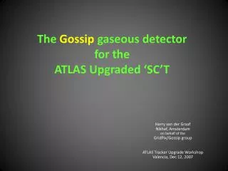
Straw man Layout All silicon detector to replace the current pixel, SCT and TRT: - pixels, - short strips(2.5cm) - long strips (10cm)
Environmental parameters NIEL 1016 Radiation for 3000 fb-1 TID 1015 • Running up to 3000 fb-1 • Design for 6000 fb-1 • Should take about 6 years (?) hadron rate for SEE • Detector temperature ~-30oC • Magnetic Field ~2T 1014
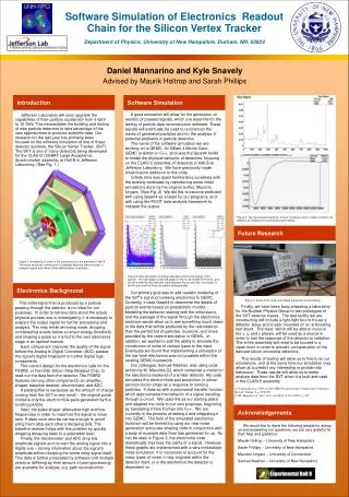
Silicon sensors Carbon honeycomb or foam Carbon fiber facing Bus cable Coolant tube structure Hybrids Readout IC’s Stave concept • Modules on fully integrated staves • Double sided • 1 to 2-m long • LS modules 10 x 10 cm2; 1280 strips (10-cm long, 80 µm pitch) • SS modules 10 x 10 cm2; 5120 strips (2.5-cm long, 80 µm pitch) 10 cm 1 to 2 m
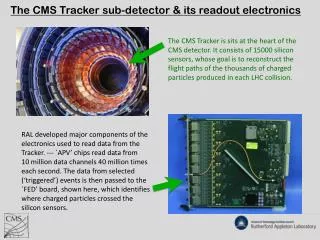
Strips Detector in numbers • Current SCT detector • 4088 modules • 49k 128-channel FEIC • 6.3M channels Long Strip Cylinders (4 meter length) Short Strip Cylinders (2 meter length)
Working Assumptions • Binary readout as in the current detector • 1 hit = 1 bit • Read-out architecture as identical as possible for the strips and the pixels • Avoid extra design diversity • Share as much as possible design efforts and costs • From the front-end electronics up the off-detector electronics • Material budget is a key element for the upgraded tracker • Solutions minimising the amount of material always preferred • Extremely harsh radiation environment for the front-end electronics • High level of single event upsets expected. • Read-out architecture as simple as possible; complex tasks such as partial event building, data integrity check, etc. to be avoided • Amount of services connected to the tracker to be kept as low as possible • To maintain an overall low material budget • Available volume for services routing severely limited
Readout Organisation Generic readout model • In the current detector the readout unit is the module • Large number of low speed readout links • Large number of power supply lines • Not affordable for the upgrade • Hierarchical readout scheme • FEIC • Module controller • Stave controller (GBT) • Low number of high speed links
Module #1 Module #2 Module #10 Cooling In TTC, Data ( & DCS) F Opto fibers E SC I (DCS link) C DCS DCS env. IN s interlock Cooling Out SC MC Service bus Hybrid PS cable Readout Organisation (Barrel Strips) • Half single sided stave as a readout unit • Readout hybrids as sub-elements • 2 hybrids with 20 FEICs per module for SS • 1 hybrid with 10 FEICs per module for LS Short Strip Single Sided Half Stave
Quantity of Data Simulation for worst case scenario: 1035 cm-2 luminosity 50 ns BC period (400 overlapping events per BC) Short Strips 0 hit 41% 1 cluster 34% >1 clusters 21% A. Weidberg etal. Number of hits per FEIC Event size for a short strips module (40 128-channel FEICs). Current ATLAS SCT detector coding scheme Mean size ~1600 bits A. Weidberg etal.
Module #1 Module #2 Module #10 Cooling In TTC, Data ( & DCS) F Opto fibers E SC I (DCS link) C DCS DCS env. IN s interlock Cooling Out SC MC Service bus Hybrid PS cable Data Rates • Long strips and short strips are well balanced • 400 versus 380 FEIC • Numbers without so much safety margin • Detector layout very likely to change • L1A rate could increase • Luminosity could increase • Data format might change • Pixel will require more bandwidth • Better design for more x2 160 Mbits/s 800 bits/event 100kHz L1 rate 80 Mbits/s 1600 bits/event 100kHz L1 rate 160 Mbits/s 1.6 Gbits/s 3.2 Gbits/s 1.6 Gbits/s (20 * 80 Mbits/s) 3.2 Gbits/s
Data Links • FEICs to MC • Electrical, 160 Mbits/s • MC to SC (GBT) • Electrical, 160 Mbits/s • Up to 20 links per half single sided SS stave • DC balanced code mandatory if serial powering is used, desirable in all cases • On-going work to assess what is achievable at different places • Optical links at >3.2 Gbits/s • Rely on the versatile link project
TTC Links • The TTC links are used to transmit to the front-end: • A clock synchronised with the beam (either the LHC clock or a multiple of it) • The L1A • Synchronous commands such as the bunch counter reset (BCR) or the event counter reset (ECR) • Control data to be stored in the FEICs, MCs and SMCs (e.g. threshold, masks, …) • Unidirectional links to minimise the number of lines • To read a register, command transmitted on TTC link, data transmitted on the read-out data link • TTC links bandwidth dictated by : • Clock frequency to be transmitted • Might be better to transmit a clock at higher frequency than the BC to be used directly by the readout logic (e.g. 160 Mhz if reading out at 160 Mbits/s. Avoid some PLL) • Necessity to transmit simultaneously the L1A and commands (e.g. Bunch Counter Reset) • Need for forward error correction to fight SEUs • Need for DC balanced codes and self clock recovery protocols • Bandwidth greater than or equal to 80 Mbits/s
Electrical Links • Protocols not defined • Clock and data separated versus single encoded link • Several low speed links versus a single high speed • Multi-drop or point-to-point • A few pictures of some promising tests 320 Mbits/s on a 60-cm Kapton tape with 4 loads V. Fadeyev 80 Mbits/s on an hybrid with 10 and 20 FEICs A. Greenall
Need for Redundancy? • Redundancy has a lot of impact on the readout architecture • Possible schemes for redundancy on the hybrids shown • Full redundancy required for the optical links (?) • Difficult to implement redundancy without increasing the number of ASICs or the amount of services • Some work necessary to assess the needs • Impact of loosing a FEIC, a readout hybrid, a half single sided stave • Define the maximum losses allowed within the life time • Define the minimum reliability level needed to be better after the life time of the experiment Possible redundancy schemes to cope with the loss of a FEIC or of a Module Controller
Data Format • Data format used in the current detector is highly optimised in size • Necessary to look at each single bit to know what it is and what is following and requires synchronisation between FEICs • “On the fly” event building and decoding • Might be a problem when a large amount of SEU are expected • Could be better to consider the system as a network and to push packets of data from the FEIC up to off-detector electronics • Pros and cons • Enough to only protect the headers against errors • Data unprotected • No synchronisation expected in the data transmission in the FE • System cannot hang • More complex task in the off-detector electronics • A lot of resources available in big FPGA • Extra data volume • To be simulated
Integrated with the readout or separated? • In the current detector, a lot of direct connections of sensors • Not applicable for the upgrade • A lot of discussions concerning the need for a fully separated DCS system • Separately powered and separate communications • Separate ASICs • Additional services…. • Still possible to run safely the detector even with the DCS integrated in the readout
Module #1 Module #2 Module #10 Cooling In TTC, Data ( & DCS) F Opto fibers E SC I (DCS link) C DCS DCS env. IN s interlock Cooling Out SC MC Service bus Hybrid PS cable Mode of Operation Humidity sensor Temperature sensors (cooling pipes and Stave Controller) • A few sensors directly connected • Used also for interlock • Powering sequentially the different components only when it is safe to do so • Note that it is easy to do with DC-DC converters but may be less with serial power • DCS functionalities in the module controllers and the stave controllers • Separation of the DCS data and the readout data in the off-detector electronics • Does not require the DAQ to work
Total Power for the Strips • Assumptions: • Pessimistic 1.5mW [1mW] per channel for the strip FEIC and 1.3V Vdd • 150mA [100mA] per 128-channel FEIC. • Total current (for the barrel and both end-caps): 48.5kA [33kA] • 80% efficiency of front-end power devices would lead to 78.5kW [52kW] dissipated in the tracker volume • 70% efficiency would lead to 90kW [60kW] • Current SCT and TRT detectors are fed with about 12kA • Assuming the amount of services cannot be increased, the powering scheme to be used must limit the amount of current to be fed at that level • That’s about 1/6th (1/5th) of the current needed by the front-end electronics. Hence either a factor 5 to 6 (at least) DC-DC conversion or a serial powering scheme of at least 5 to 6 modules has to be used.
DC-DC or Serial Power • Developments are on-going: serial powering and DC-DC conversion • Cf yesterday power sessions • Reducing the current to be fed by a factor of 5-to-10 minimum is reachable with both solutions • DC-DC converters offer some interesting flexibility • Can separate different supplies easily • Analog – digital saving in overall power • Stave controller, module controller and FEICs capability of controlling the operation • Radiation hardness not solved • Serial powering scheme has some system issues which are being tackled • Options to be kept opened for a while • Real estate is an important issue for both solutions
Space available for the power devices • Readout hybrid with 20 FEIC (ABCn 0.25 device) • Not so much space for the power devices and the module controller…
Rough Estimate • Services for the barrel strips at the entrance of the tracker volume • 1 mW/ch • DC-DC or serial power introduces a factor 10 saving on the current • 2-V drop max • Packing factor of 2 LV is still the dominant part by far
Total Fantasy • LoI, TP and TDR in 2009, 2010 and 2011 • LHC stop: October 2016 • SLHC start: Spring 2018 • Tracker installation: January 2017 (?) • Stave assembly start: January 2013 (?) • Very little time left for fully specifying the components and designing them • Choice of technology to be used (130nm or 90nm or lower) as late as possible • Most of the work done in 130nm so far • Some early work with 90nm (or lower) necessary to be able to make the decision in due time • Analogue performances • Radiation hardness
Total Fantasy (cont) • Architecture definition complete with options Nov-08 • Decision on options (powering, electrical links, opto) Dec-09 • Component specifications complete Feb-10 • Prototype sensitive blocks (design, MWP fab, test) Sep-08 to Dec-09 • Prototype complete component design, fab and test Feb-10 to Aug-11 • Stave assembly & test (system test of electronics) Aug-11 to Feb-13 • Pre-production component design, fab and test Feb-12 to Feb-13 • Pre-production stave assembly & system test Feb-13 to Jul-13 • Production Readiness Review Aug-13 • Component Production • First production wafer batch (fab and test) Aug-13 to Feb-14 • Deliver first production batch to module assembly sites Feb-14 • Start component series fabrication Sep-13(Assumes no design change from pre-production) • Start of component series delivery to assembly sites Apr-14 No contractual value!
ASICs developments and specifications • Working document on architecture available since about a year • ATL-P-EN-0001 (A. Grillo, G. Darbo, Ph. Farthouat) • Reviewed and presented to the collaboration • Two working groups in place to try and define more precisely the specifications of the different components. One for the pixels and one for the strips • Inputs to the “common projects” teams (e.g. GBT) • ~350k FEIC but only ~20k MC and ~5k SC(GBT) • ABCn 0.25 chip as test vehicule for sensor studies • Also contains some features for testing different power schemes and readout speeds • Preliminary study of the front-end part (preamplifier-shaper-discriminator) in 0.13 • Very good power performances: <200µW per channel • See J. Kaplon presentation of Tuesday • Evaluation of SiGe
Fixed Barrel Length • SS longer more modules more data (+20%) • LS shorter less modules and less data
The readout architecture of the ATLAS upgraded tracker has to be different from the current one • Detector organised in staves. Hierarchical readout following this segmentation • Fewer but higher speed links • Some elements of the readout are not to be produced in very high quantity • Points towards common solutions with CMS and others • Power distribution requires special efforts to maintain reasonable services • Saving factor 5 - 10 on the current • Schedule looks uneasy • Not so much time for the electronics development • Decision on technology to be used for the FE electronics at the latest in 2012