Download
1 / 115
1.19k likes | 1.48k Vues
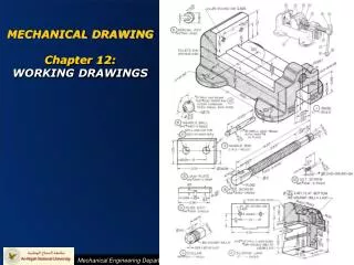
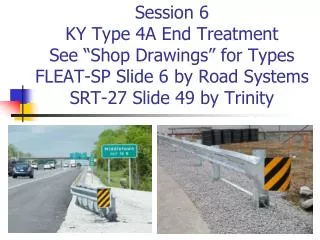
Session 6 KY Type 4A End Treatment See “Shop Drawings” for Types FLEAT-SP Slide 6 by Road Systems SRT-27 Slide 49 by Trinity. Standard Drawing RBR-035 Guardrail End Treatment Type 4A MUST use App. Shop Drawings.

E N D
Session 6KY Type 4A End TreatmentSee “Shop Drawings” for TypesFLEAT-SP Slide 6 by Road SystemsSRT-27 Slide 49 by Trinity
Standard Drawing RBR-035 Guardrail End Treatment Type 4A MUST use App. Shop Drawings
RBR-035 -KYTC Pay Limits for the Type 4A is 37'-6” even though the FLEAT Shop Drawing says 12’ 6”?
Installation Instructions for Proprietary Guard Rail End Terminals • This Std Draw Note appears on each Proprietary End Treatment used in KY - “The Manufacturer SHALL furnish two (2) sets of shop plans to the contractor with each installation” • Each Proprietary End Treatment “see shop drawings” • Added to Sect 719.03 of 2012 Std Specs: “Proprietary end treatments SHALL be installed according to the manufacturer’s assembly or installation instructions” • SHOULD NOT LET THE CONTRACTOR BEGIN INSTALLATION BEFORE SUPPLYING YOU WITH THESE SHOP PLANS & INSTALLATION INSTRUCTIONS – Both you and the contractor need these documents to properly do your jobs of installing and inspection propriety guardrail end terminals
How do you know which version of a Proprietary Guardrail End Treatment KY is Using? • Go to the KYTC Div of Design Home Page http://transportation.ky.gov/Highway-Design • On the right click on Standard Drawings • Brings up: • Standard Drawings • Active Sepia List • Approved Shop Drawings - Click • The drawings show the version 350, SP, 27 etc. • Good general information on the Shop Drawing
Type 4A End TreatmentFLEAT-SP (Std Post) Installationhttp://roadsystems.com/fleat.html
FLEAT & SKT-SP Road Systems http://roadsystems.com/pdf/fleat/SP-Installation-Manual.pdf SKT-SP & FLEAT-SP A very easy to follow “Assembly Instructions” With Drawings and Photos As I noted in the Type 1 Discussion we will cover both the Type 1 SKT-SP and the Type 4A FLEAT-SP Installation together with the Type 4A Discussion
FLEAT FLared Energy Absorbing TerminalAbsorbs Energy by Kinking & Extruding the Rail Thru Impact Head
The FLEAT Extrudes the Rail Toward Traffic in a Tight RollThru Impact Head and Feeded Chute
Type 4A FLEAT-SPhttp://roadsystems.com/fleat.html • FLEAT-SP (FLared Energy Absorbing Terminal – Standard Post System) is an energy-absorbing flared terminal -NCHRP 350 APPROVED • Flare is straight and the offset is variable between 2'-6" and 4'-0” - KY only uses 4’ • No strut, but does have a soil plate at Post 1
FLEAT Variable Offset KY = 48” 2’-6” 4’-0” Road Systems, Inc.
Type 4A FLEAT-SP http://roadsystems.com/fleat.html • FLEAT-SP Guardrail has SLOTS Toward The Impact Head • Cable Anchor Bracket has Special Bolts with Widened Shoulders
Installation Procedures for FLEAT-SP and SKT-SP • Install standard steel guardrail posts #3 - #6 (on a straight 48” flair Post 7 to Post 1 FLEAT) • Install breakaway steel end posts #1 and #2 • Install guardrail. All posts are spaced at 6'-3" • Install cable anchor bracket • Install the SKT-SP or FLEAT-SP impact head • Install cable assembly
Install Post 3-6 Requires Standard Post at 6’3” Post Spacing
NO CURVES Energy Absorbing End Treatmentts STRAIGHT FLARE / NOT CURVED
Post 1 and 2 are Hinged to Facilitate Bending of the Post Upon ImpactPost 1 has a Soil Plate - Downstream
Post 1 and 2 are Hinged to Facilitate Bending of the Post Upon ImpactPost 1& Post 2 are NOT the Same • Post 1 and 2 are NOT the same • Post 1 and 2 are both two part Post that Bend or Hinge on Impact • Install the bottom of the Post before connecting the Top portion of each Post
IMPORTANT SKT-SP and FLEAT-SPAssure the 5/8” or 3/4” Hinge Bolts are at the Proper Locations
IMPORTANT SKT-SP and FLEAT-SPAssure the 5/8” or 3/4” Hinge Bolts are at the Proper Locations • Post 1 – 5/8” x 8 ½” bolt, nut & 2 washers are on UPSTREAM side of the post (toward Impact Head) • Post 2 - ¾” x 8 ½” bolt and nut (no washers) on DOWNSTREAM side of the post (away from Impact Head)
Post 2 is Hinged so it will bend over upon impact, slot allows the post to release from the guardrail bolt Traffic
Post 2 -Assure the Guardrail Connection Bolt Slot is Facing Post #1 – Guardrail Connection Bolt slides out upon Impact
Post 2 is Installed Incorrectly!! Top and Bottom are Installed Backward – Post Cannot Hinge properly – GR Bolt Cannot Release Properly Traffic
Post 3-6 require Standard Post With 8” Offset BlocksPost 1 & 2 no Offset Blocks Therefore Post 1&2 do not line up with other Post
Install the rail from Post 6-3 with 8” Offset Blocks and Post 1-2 No Offset Blocks Do NOT Attach Guardrail to Post 1 or 3 (Type 4A FLEAT)
Type 1 “SKT-SP” Guardrail Bolt is Connection to Post 3 - Correct Installation SKT-SP Connect the Guardrail to Post 3 as shown Post 3
Type 4A “FLEAT-SP”NO Guardrail Bolt Connection to Post 3 - Incorrect Installation FLEAT-SP Do NOT Connect the Guardrail to Post 3 just Connect the Block Out Post 3
FLEAT-SP – Guardrail Correctly “NOT” Bolted to Post 3 – just Connect Offset Block to Post 3
Guardrail Post 1-3 has 10 slots to Facilitate Bending the Rail as it Extrudes thru the Impact Head and 8 Bolt Holes
Cable Anchor Bracket – Install Shoulder Bolts Washers, Nuts and Bracket Bolts Heads on Inside of Rail NOT Outside Note: 2 washers on each bolt
Cable Anchor Bracket – Designed to Release During an Impact Bracket Bolted to Rail (8 places) Bracket rest on Shoulders of Bolts Road Systems, Inc.
Finger tighten Bolts & Washers – align slots on bracket with shoulder of bolts - tap into place with a hammer then tighten bolts
Note how the Cable Anchor Bracket rest Snugly on the Shoulders of the Special Bolts
Assure Anchor Bracket is fully seated on Shoulder Portion of the Cable Anchor Bolts - Openings on Cable Anchor Bracket toward Post 1Bolts Installed Incorrectly – Nuts on Inside Bolt head placed on Front Side of Rail without Washer Bolts installed backwards with nuts on inside
SKT & FLEAT - Post 1 is HingedArm on Impact Head Helps Bend Post
The Guardrail is NOT attached to Post 1. The Impact Head is.
Impact Head Attachment @ Post 1, 5/16” Grade 5 bolts need 2 washers each (1 under nut & 1 under bolt head) and they need tightening
Improper Installation - Extruder Head not Pushed all the way on
SKT-SP Cable feed inside/thru the Feeder Chute FLEAT-SP cable does NOT
8”x8” Bearing Plate oriented Properly with Washer (5” up) - need restraining tie to keep Bearing Plate from Twisting
Orientation of Bearing Plate Which Bearing Plate is almost Correct? Road Systems recommends a Restraining Tie
Tighten Anchor Cable – Using Vice Grips, on Shank not on the Cable, to prevent twisting of the Cable
FLEAT-SP Checklist • Rail height is 27 ¾” Minimum • No Curved Rail SKT-SP 50’ FLEAT-SP 37’ 6” • Guardrail is NOT attached at Post 1 & 3 • End Rail Panel has Special Slots • Hinge Bolt @ Post 2 is Downstream • Hinge Bolt @ Post 1 is Upstream • Bolt Slots in Post 2 Face Upstream
FLEAT-SP ChecklistContinued • Stubs of Post 1&2 do not stick up 4” • Straight 4’ Flare • Bolts Holding Impact Head are Properly Installed and Secure (2 washers each) • 8”x8” bearing Plate Oriented with 5” up • Cable Anchor Brackets Properly Installed Such that Bracket is Fully Seated on the Bolt Shoulders • Cable Taught
Road Systems Assembly Instructions for SKT-SP and FLEAT-SP • This is a very useful and well done document • http://roadsystems.com/pdf/fleat/SP-Installation-Manual.pdf
Type 4A – SRT-27 Trinity Highway productshttp://www.highwayguardrail.com/products/cb.html