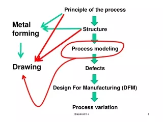
Drawing Standards for Technical Drawings
Learn about drawing standards used worldwide to ensure consistent representation in technical drawings. Explore codes and conventions governing various aspects of drawings such as formats, scales, line types, and meanings.

Drawing Standards for Technical Drawings
E N D
Presentation Transcript
Drawing standards are used so that drawings convey the same meaning to everyone who reads them. Introduction Standards are set of rules that govern how technicaldrawings are represented.
Full name Country Code USA American National Standard Institute ANSI มอก. สำนักงานมาตรฐานผลิตภัณฑ์อุตสาหกรรม Thailand Japanese Industrial Standard Japan JIS British Standard UK BS Australian Standard Australia AS Deutsches Institut fürNormung Germany DIN International Standards Organization ISO Standard Code
Contents Code number Partial List of Drawing Standards มอก. 210 2520 วิธีเขียนแบบทั่วไป : ทางเครื่องกล มอก. 440 ล.1 2541การเขียนแบบก่อสร้างเล่ม 1 ทั่วไป มอก. 446 ล.4 2532 ข้อแนะนำสำหรับการเขียนแผนภาพ วงจรไฟฟ้า มอก. 1473 2540การเขียนแบบเทคนิค การติดตั้ง สัญลักษณ์สำหรับระบบท่อของเหลว ระบบทำความร้อน การระบายอากาศ และระบบท่ออากาศ ที่มา : http://library.tisi.go.th/data/lib_resources/pdf/catalog-online49/tis/02_ICS.pdf
Contents Code number Partial List of Drawing Standards JIS Z 8311 Sizes and Format of Drawings JIS Z 8312 Line Conventions JIS Z 8313 Lettering JIS Z 8314 Scales JIS Z 8315 Projection methods JIS Z 8316 Presentation of Views and Sections JIS Z 8317 Dimensioning
Drawing Sheet A4 Trimmed paper of a size A0 ~ A4. A3 Standard sheet size(JIS) A4 210 x 297 A3 297 x 420 A2 420 x 594 A1 594 x 841 A0 841 x 1189 A2 A1 (Dimensions in millimeters) A0
Orientation of drawing sheet c d d c c Sheet size c (min) d (min) A4 10 25 A3 10 25 A2 10 25 A1 20 25 A0 20 25 1. Type X (A0~A4) 2. Type Y (A4 only) Drawing space Drawing space Border lines Title block Title block
: Drawing Scales Length, size Scaleis the ratio of the linear dimension of an element of an object shown in the drawing to the real linear dimension of the same element of the object. Size in drawing Actual size
Designation of a scale consists of the word “SCALE” followed by the indication of its ratio, as follow Dimension numbers shown in the drawing are correspond to “true size” of the object and they are independent of the scale used in creating that drawing. Drawing Scales SCALE 1:1 for full size SCALE X:1 for enlargement scales (X > 1) SCALE 1:X for reduction scales (X > 1)
Continuous thick line Visible line Dimension line Extension line Leader line Continuous thin line Dash thick line Hidden line Chain thin line Center line Basic Line Types Name according to application Types of Lines Appearance NOTE : We will learn other types of line in later chapters.
Meaning of Lines Visible lines represent features that can be seen in the current view Hidden lines represent features that can not be seen in the current view Center linerepresents symmetry, path of motion, centers of circles, axis of axisymmetrical parts Dimension and Extension linesindicate the sizes and location of features on a drawing