Download
1 / 40
400 likes | 415 Vues
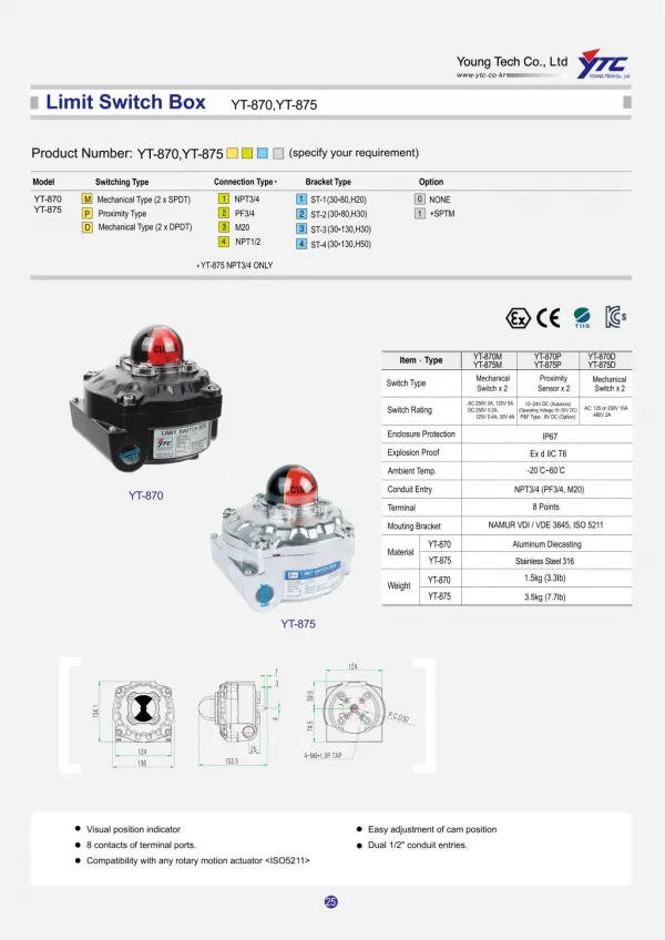
"Rotork Soldo Control SF Limit switch box designed for safe and hazardous areas, provides a visual and electrical remote position feedback on automated valves. Available in die cast aluminum with different lid choices, from the same enclosure material, for a complete metallic device, to the transparent polycarbonate cover or to a flat lid without visual indication. Designed for weather proof applications, it can also matches the Ex ia IIC T6 standards with the integral intrinsically safe certification, covering both enclosure and electrical components inside. The Soldo multi-application limit switch box solution, covering from industrial automation to food and beverage, from chemical to naval, from Oil and Gas, both onshore and off shore, to Petrochemical industries.<br><br>YTC India are Exclusive distributors, Supplier & Dealers in India for YTC make pneumatic positioners, air filter and pressure regulators, limit switch box, electro pneumatic positioners valve and calibiration positioners, hart and ip converters air and vaccum boster and valves catalog, manuals. YTC Korea products confirm to best International quality and are at par with norgren, parker, abb, rotex, siemens, samson, shavo, smc, watson smith, watts, siemens 760, 6dr5210, ps2, sipart, tzidc in Ytc India.<br><br>For More Details Visit Our Website :- www.ytcindia.com<br>Email Us At :- info@ytcindia.com , ytcindia9@gmail.com<br>Tel. No.: 91-11-2201-4325,4327,65094516

E N D
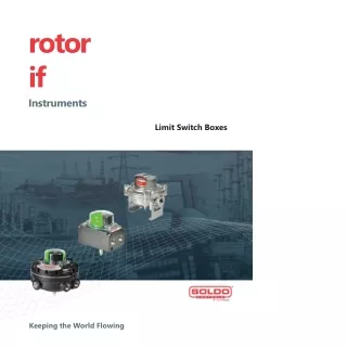
rotorif Instruments Limit Switch Boxes A rotor# Brand Keeping the World Flowing
M _ ® rotorif Keeping the World Flowing RELIABILITY IN FLOW CONTROL CRITICAL Reliable operation when it matters Quality-driven global manufacturing Products designed with 60 years of industry and application knowledge. Research and development across all our facilities ensures cutting edge products are available for every application. Assured reliability for critical applications and environments Whether used 24/7 or infrequently, Rotork products will operate reliably and efficiently when called upon. Customer-focused service worldwide support Solving customer challenges and developing new solutions. From initial enquiry through to product installation, longterm after-sales care and Client Support Programmes (CSP). Low cost of ownership Long-term reliability prolongs service life. Rotork helps to reduce long term cost of ownership and provides greater efficiency to process and plant. f i Limit Switch Boxes 2
Limit Switch Boxes Section Page Rotork - Keeping the World Flowing 2 Rotork Instruments 6 Product Overview Chart 8 Twin Shaft Design 10 Visual Indication 11 Approvals and Marking 12 Switch and Sensors 14 Position Transmitters 15 Special Options 16 HART Communication 17 Foundation Fieldbus Communication 17 AS-i Communication 18 Profibus Communication 19 Section Page Product Ranges 20 SP - SM limit switch box series 20 SF - SS - SB limit switch box series 22 HW limit switch box series 24 SK - SQ limit switch box series 26 SY - SW limit switch box series 28 SX - SH limit switch box series 30 BM - TB limit switch box series 32 ES Easy limit switch box 34 Mounting Kits 36 Appendix A: Equipment Certification Requirements for Hazardous Locations 38 Comprehensive product range serving multiple industries Improved efficiency, assured safety and environmental protection. Rotork products and services are used throughout industry inclusive of Power, Oil & Gas, Water & Wastewater, HVAC, Marine, Mining, Pulp & Paper, Food & Beverage, Pharmaceutical and Chemical industries around the world. Market leader technical innovator The recognised market leader for 60 years. Our customers have relied upon Rotork for innovative solutions to safely manage the flow of liquids, gases and powders. Global presence local service Global company with local support. Manufacturing sites, service centres, sales offices and Centres of Excellence throughout the world provide unrivalled customer services and fast delivery. Corporate social responsibility A responsible business leads to being the best business. We are socially, ethically, environmentally responsible and committed to embedding CSR across all our processes and ways of working. >] Keeping the World Flowing 3
M _ ® rotorif Keeping the World Flowing ▲ Industry knowledge Our engineering and application knowledge base, built over 60 years, allows us to provide innovative and reliable solutions for all flow control applications. We work across the globe, servicing a diverse range of markets and critical applications. Our experience of flow control is second to none. Active in every industry and market sector around the world. Serving customers and working with partners. Improving efficiency, assuring safety and protecting the environment. Limit Switch Boxes
Oil & Gas Water & Wastewater - Rotork products are used on modern state-of-the-art water treatment and distribution processes, which maximise existing resources such as desalination plants and water re-use projects, together with conventional water and wastewater plants. • Sludge and sewage treatment • Water treatment, desalination and re-use • Environmental control • Dams, reservoirs and irrigation Rotork products are used on upstream, midstream and downstream activities, ranging from offshore production facilities, to refining and processing, to transportation, storage and distribution. • Onshore and offshore production • Refining and petrochemicals • Distribution and storage • Pipelines • LNG liquefaction and regasification • Unconventional oil & gas Power Rotork products are found in traditional power stations, • Marine including nuclear power stations where its products are • Pharmaceutical certified for use both inside and outside containment. • hVAC They are also used for renewable energy generation . systems such as thermal solar plants, and emission • Mining reduction processes such as flue gas desulphurisation. • Biomedical • Rail • Conventional fuels • Nuclear energy • Pulp & Paper • Concentrating solar power • Food & Beverage • Geothermal and other renewables >] Keeping the World Flowing 5
Rotork Instruments rotorif Instruments Rotork Instruments are specialist manufacturers of products for flow control, pressure control, flow measurement and pressure measurement. Our solutions are trusted wherever there is a need for high precision and reliability, including pharmaceutical, biomedical, oil & gas and manufacturing industries. We have production facilities throughout the world, complemented by a large network of distribution and support centres. A full listing of our worldwide sales and service network is available on our website at www.rotork.com Worldwide Industry and Application Experience With nearly 60 years of extensive knowledge and experience, Rotork has provided products and services worldwide for virtually every industrial actuator application. Rotork Instruments offers a range of precision control and valve accessory products through our prestigious brands, including Fairchild, YTC, Soldo®, Midland-ACSTM, Bifold®, Orange, M&M, Alcon and RI Wireless: Instrument Valves • Valve actuation accessories • Solenoid valves • Piston valves • Instrument valves • Medium pressure valves • Subsea valves and connectors Controllers • Valve positioners • Rail systems • I/P and E/P converters • Fire protection Measurement • Valve position sensors • Transmitters and switches Instrument Pumps • Pumps • Intensifiers and accumulators BffofeJ a, Arotont Brand FA. I Ft CHILD precision pneumatic 4 motion control lalaramllaaml A latent Brand AmtOTH-Brand Rotork Instruments is proud to offer a diverse range of products which serve many different duties in a wide variety of applications. We also offer a factory customisation service to create one-off units to meet specific needs. f i Limit Switch Boxes 6
Rotork Instruments A rOtOrK Brand The Soldo range of limit switch boxes, proximity sensors, and accessories offers a variety of options. Soldo specialises in the design and manufacture of control accessories for valve automation, providing high quality products and services that guarantee a link between the control room and automated process valves. Product development programs ensure Soldo is always ready for new markets and applications and able to meet or exceed customer requirements. Soldo products are valued by customers for their advanced design and capabilities including: Versatility From cost effective, when price is a concern, to corrosion resistant and explosionproof, when harsh environments are encountered, Soldo products provide the protection and automation that each application demands. Unique Design Features Soldo units are a step above the competition with unique split shaft designs. This allows installation where space is a factor and where a low profile limit switch box is not preferred. Soldo limit switches also have easy-set 3 degree cams for independent tool free adjustment. Simple Installation Pre-wired PCB switch modules ensure installation is worry free and allows easy installation and wiring directly into terminal strips. The pre-wired boards are conformal coated for environmental protection. Soldo also offers a full line of mounting brackets for all models that do not come with an integral mounting kit. Italy (manufacturing plant) tel: +39 035 451161 email:sales.instruments-italy@rotork.com USA tel: +1 (336) 659 3400 email:sales@soldousa.com Full contact details and company information is available online at www.soldo.net Keeping the World Flowing
00 O Q. C n r+ o < n> < n>' Limit Switch Boxes n =r QJ “D O ?
Product Overview Chart Copper free aluminium or 316 stainless steel Copper free aluminium or 316 stainless steel Copper free aluminium 316 stainless steel or aluminium Aluminium 316L stainless steel 316 stainless steel 316 stainless steel Housing Copper free aluminium or 316 stainless steel Copper free aluminium or 316 stainless steel Copper free aluminium 316 stainless steel or aluminium Aluminium 316L stainless steel 316 stainless steel 316 stainless steel Cover IP 66 / 67 optional IP68 IP 66 / 67 optional IP68 IP 68 subsea option available IP Rating P 66 / 68 P 66 / 68 IP67 IP 67M P 68 IP 68 SIL Rating up to: SIL3 SIL3 SIL3 SIL3 SIL3 SIL3 SIL3 SIL3 ATEX, IECEX option Exd IIC T6 Exia IIC T4 Exd IIC T6 Exd IIC T6 Exd IIC T6 Exd IIC T6 Exd IIC T6 Exd IIC T6 cULus option Class 1/2 Div 1/2 Class 1/2 Div 1/2 Class 1/2 Div 1/2 Class 1/2 Div 1/2 Class 1/2 Div 1/2 EAC option ✓ ✓ ✓ ✓ ✓ ✓ ✓ ✓ CCOE option ✓ ✓ ✓ ✓ INMETRO option ✓ ✓ ✓ ✓ ✓ NEPSI option ✓ ✓ ✓ ✓ ✓ ✓ 3D ✓ ✓ ✓ ✓ Flat Multi Port Valves ✓ ✓ ✓ ✓ ✓ ✓ ✓ ✓ None Electro mechanic ✓ ✓ ✓ ✓ ✓ ✓ ✓ ✓ ✓ ✓ ✓ ✓ Magnetic ✓ ✓ ✓ ✓ ✓ Inductive ✓ ✓ 4-20 mA Communication Protocols ✓ ✓ Twin Shaft Design ✓ ✓ ✓ ✓ Temp. Max Range -55 to +105 °C (-67 to +221 °F) -55 to +105 °C (-67 to +221 °F) -60 to +105 °C (-76 to +221 °F) -60 to +105 °C (-76 to +221 °F) -50 to +105 °C (-58 to +221 °F) -65 to +150 °C (-85 to +302 °F) -40 to +105 °C (-40 to +221 °F) -40 to +105 °C (-40 to +221 °F) Integrated Mounting Kit Optional Optional Keeping the World Flowing 9
Twin Shaft Design The innovative twin shaft design provides user friendly installation, replacement, calibration and operation. Splitting the limit switch box into two halves improves the sealing arrangement to extend operating life in harsh or severe environments whilst reducing the possibility of failure. Features: • Shaft sections mate together with a simple and reliable mechanical linkage • Each half of the switch box mechanically retains the shaft, preventing loss of components during disassembly • The shaft is completely sealed from the external atmosphere, avoiding contamination of the lubricating grease • The switch position indicator is permanently fixed to the top shaft to guarantee alignment during reassembly • Electrical components are completely sealed once both halves of the switch box are reassembled Jo yellow 3 vetais exposed to atmosph ere ealing / Upper shaft irmly f tted on the cover Bronze bushing Upper shaft Bronze bushing I Sealing Lower shaft firmly fitted on the body No yellow metals exposed to atmosphere' Lower shaft f i Limit Switch Boxes 10
Visual Indication Ever increasing market requirements push Rotork to develop innovative solutions for position indication. Code selection guide Code Keeping the World Flowing 11
Approvals and Marking Electrical components require a specific protection method in explosive atmospheres due to the presence of gas or dust. Different geographical regions are subject to local standards and certification to guarantee safety against explosion risks. Rotork offers a complete range of certifications, covering worldwide requirements. Hazardous Areas and Ignition Explosions in hazardous areas occur when flammable liquids, vapours, gases or combustible dusts are mixed with oxygen and an ignition source, causing a fire or explosion. Limiting oxygen or gas is difficult, therefore the solution is to control the ignition source or safely contain the explosion. Safe Area Hazardous Area ZONE 1-21 Intrinsically Safe Protection Method The intrinsically safe protection method works by reducing the power supplied into the hazardous area with an Ex'ia' barrier. The power reaching the hazardous area and the device is insufficient to generate a spark thus avoiding ignition. Control Room Intrinsically Safe Barrier Explosionproof Protection Method The explosionproof protection method guarantees that in case an explosion should happen, it will be contained inside the enclosure. All mechanical joints of the device, such as the lid to body connection, cable entries and shaft assembly have flame paths, designed and certified to ensure an explosion is contained. f i Limit Switch Boxes 12
Approvals and Marking Code selection guide Code: SF 70 No SIL approval SIL2 approval SIL3 approval 0 A 1 1 EAC CCOE INMETRO NEPSI safe area Intrinsically safe Non-incendive (3GD Exn) g0 f0 h0 G1 | H1 SP/SM !■ SB !■ z0 I0 ■ UA E9 Safe area Intrinsically safe Non-incendive (3GD Exn) Non-incendive (2D Extb) Non-incendive (3D Extc) W0 B1 B6 X1 D1 E1 : : SF/SS s9 ■ dd B5lC5 W0 |0 y0 Safe area Non-incendive (3GD Exn) Non-incendive (3D Ext) i B6 |c6 ! B5 C5 HW rZ0 ■ ■ " |Q2" |r2" Safe area Explosion / flame proof (Exd IIC) Non-incendive (Exd enclosure) SK/SQ SY/SW rZ0 Y0 Safe area Explosionproof / flameproof (Exd IIB) Non-incendive (Exd enclosure) SX rZ0 Y0 |D4 E4 U7 S7 T7 G4 U8 |S8 |t8 P4 Safe area Explosionproof / flameproof (Exd IIB + H2) Non-incendive (Exd enclosure) L4 SH G4 F4 I4 O4 P4 Safe area Intrinsically safe Explosionproof / flameproof (Exd IIC) Non-incendive (Exd enclosure) BM/TB 0 |0 |0 ■ !■ I02|p2 Safe area Explosionproof / flameproof (Exd IIC) Non-incendive (Exd enclosure) X2 I E2 U7 I T7 F2 H2 ES U8 I T8 * Excluding SQ and TB series ** SY SW series only Keeping the World Flowing 13
Switch and Sensors Rotork Instruments offers one of the widest ranges of switch in the market. Rotork always provides the best switch or sensor solution for your specific application. Soldo limit switch boxes can include mechanical, magnetic or inductive proximity switches to fulfil your plant feedback requirements. With over 20 years experience in valve automation feedback, Soldo offers a complete selection of magnetic limit switches to meet the most critical and demanding requirements. Inert gas hermetical sealing, high power loops, different contact forms and alternative materials are all satisfied with high quality Soldo switches. *8Suitable for fire fighting applications &Suitable in arctic application Suitable in Exia application Hermetically sealed Electro mech. switches Code: SPDT switches Code 01 • SPDT silver plated snap action switch • High power loop: rating DPDT switches Code 1F • DPDT silver plated snap action switch • High power loop: rating Code 5P SPDT silver plated snap acting switch High power loop: rating up to 5A @ 250 VAC Temperature range: -50 to +204 °C (-58 to 399 °F) up to 5A @ 250 VAC - 0,6A @ 125 VDC • Temperature range: -40 to +125 °C (-40 to +257 °F) up to 5A @ 250 VAC, 0.1A @ 80 VDC • Temperature range: -40 to +120 °C (-40 to +248 °F) Code 06 <§> Short time temperature range: Maximum 250 °C (482 °F) for 2 hours Maximum 300 °C (572 °F) for 70 minutes Code 03 • SPDT gold plated snap action switch DPDT gold plated snap action switch % • Rating up to 3A @ 250 VAC -1mA @ 24 VDC Rating up to 0.1A @ 250 VAC, 0.1A @ 80 VDC Temperature range: -40 to +120 °C (-40 to +248 °F) • Temperature range: -40 to +125 °C (-40 to +257 °F) Magnetic switches SPDT switches CODE N1 @ • NOVA V3™ SPDT hermetically sealed DPDT switches CODE N4 • NOVA V3™ DPDT hermetically sealed CODE C4 © • SPDT hermetically sealed proximity reed switch snap action proximity switch • High power loop: rating up to 5A @ 250 VAC - 5A @ 28 VDC • Temperature range: -50 to +95 °C (-58 to +203 °F) CODE N3 snap action proximity switch • High power loop: rating up to 5A @ 250 VAC - 5A @ 28 VDC • Temperature range: -20 to +95 °C (-4 to +203 °F) CODE C8 © • Inert gas contact chamber • Rating up to 1A @ 24 VDC • Temperature range: -60 to +100 °C (-76 to +212 °F) • NOVA V3™ SPDT hermetically sealed • DPDT hermetically sealed proximity snap action proximity switch • High power loop: rating up to 1A @ 250 VAC - 1A @ 30 VDC • Temperature range: -50 to +95 °C (-58 to +203 °F) reed switch • Inert gas contact chamber • Rating up to 1A @ 24 VDC • Temperature range: -60 to +100 °C (-76 to +212 °F) Inductive sensors Amplified sensors Code 32 • 2 wires NO • LED indicator • Operating voltage 5-60 VDC • Operating current 2-100 mA • Temperature range: -25 to +70 °C (-13 to +158 °F) Code 73 • 3 wires PNP NO • LED indicator • Operating voltage 10-30 VDC • Operating current 0-100 mA • Temperature range: -25 to +70 °C (-13 to +158 °F) NAMUR Exia sensors % Code 70 €> Code 75 • 2 wires NO/NC programmable • Operating voltage 5-36 VDC • Operating current 200 mA • Temperature range: -25 to +80 °C (-13 to +176 °F) • Nominal voltage 8 VDC • Current consumption: 1mA (target detected) 3mA (target not detected) • Temperature range: -25 to +100 °C (-13 to +212 °F) Code 62 © * • Nominal voltage 8 VDC • Current consumption: 1mA (target detected) 3mA (target not detected) • Temperature range: -50 to +100 °C (-58 to +212 °F) f i Limit Switch Boxes 14
Position Transmitters If discrete feedback information box enclosure for both safe and represents 0-100% of the measurement range. With the introduction of SMART devices, HART provides digital communication overlaid on the analogue 4-20 mA signal. is not enough, Rotork can offer a complete range of analogue position transmitter options embedded within the switch hazardous areas. Analogue 4 - 20 mA current loops are commonly used for electronic signalling in industrial process control. 4 & 20 mA 4-20 mA Suitable for Exia application Code Code T0 • 4-20 mA analog output • Supply voltage 13-30 VDC • Linearity ± 0,5% on full scale • Direct or Reverse action • Temperature range: -40 to +80 °C (-40 to +176 °F) Code T4 • 4-20 mA analog output • Additional magnetic reed switches • Supply voltage 13-30 VDC • Linearity ± 0,5% on full scale • Direct or Reverse action • Temperature range: -40 to +80 °C (-40 to +176 °F) Code T1 • 4-20 mA analog output • Additional silver plated mech. switches • Supply voltage 13-30 VDC • Linearity ± 0,5% on full scale • Direct or Reverse action • Temperature range: -40 to +80 °C (-40 to +176 °F) Code T7 • 4-20 mA analog output • Additional inductive NAMUR sensors • Supply voltage 13-30 VDC • Linearity ± 0,5% on full scale • Direct or Reverse action • Temperature range: -25 to +80 °C (-13 to +176 °F) 4-20 mA HART HARFW Code H0 • 4-20 mA HART Transmitter • ATEX EEx ia IIC T6 / T4 certified • Update time 120 ms • Temperature range: -40 to +80 °C (-40 to +176 °F) Code H4 <S> • 4-20 mA HART Transmitter • Additional magnetic reed switches • ATEX EEx ia IIC T6 / T4 certified • Update time 120 ms • Temperature range: -40 to +80 °C (-40 to +176 °F) Code H1 • 4-20 mA HART Transmitter • Additional silver plated mech. switches • ATEX EEx ia IIC T6 / T4 certified • Update time 120 ms • Temperature range: -40 to +80 °C (-40 to +176 °F) Code H7 €> • 4-20 mA HART Transmitter • Additional inductive NAMUR sensors • ATEX EEx ia IIC T6 / T4 certified • Update time 120 ms • Temperature range: -25 to +80 °C (-13 to +176 °F) Foundation Fieldbus / Profibus PA Code F0 ' • Foundation Fieldbus / Profibus PA position Transmitter • ATEX EEx ia IIC T6 / T4 certified • Update time 400 ms • Temperature range: -40 to +80 °C (-40 to +176 °F) Code F4 • Foundation Fieldbus / Profibus PA position Transmitter • Additional inductive NAMUR sensors • ATEX EEx ia IIC T6 / T4 certified • Update time 400 ms • Temperature range: -25 to +80 °C (-13 to +176 °F) Code F1 • Foundation Fieldbus / Profibus PA position Transmitter • Additional silver plated mech. switches • ATEX EEx ia IIC T6 / T4 certified • Update time 400 ms • Temperature range: -40 to +80 °C (-40 to +176 °F) More options available on request. Keeping the World Flowing 15
Special Options Rotork offer a wide range of options for specific field applications. Partial Stroke Test device Code Code P0 The Partial Stroke Test (PST) device is a simple and reliable electro-mechanical system. A magnetic key initiates the test while an internal electro-mechanical system drives the actuator back to the opening position after the last position has been reached. Includes: Code P4 Magnetic reed SPDT switches Code P7 Exia inductive NAMUR sensors Surge protector devices C Code S6 Surge protectors guard the device and all inner electrical components from external power overloads. Certification is available for Exia or Exd, with components in 316 stainless steel for harsh environments protection. Includes: Code S7 Exia inductive NAMUR sensors Code SC Exia inductive NAMUR sensors tamper proof magnetic reed SPDT switches V_J End Of Line monitoring system More options available on request. f i Limit Switch Boxes 16
HART Communication The HART Communication Protocol (Highway Addressable Remote Transducer) is a hybrid, analogue and digital, industrial automation protocol. HART provides two simultaneous communication channels: the 4-20 mA analogue signal and a digital signal. The 4-20 mA signal communicates the primary measured value. Additional device information is communicated using a superimposed digital signal on the analogue one. Rotork can offer a complete range of 4-20 mA HART position transmitters with or without additional switches. Refer to the Position Sensor section for a wider list of options and code selection guide. COMMUNICATION PROTOCOL Digital Signal ‘0” ‘0” T Analog Signal Time Foundation Fieldbus Communication Rotork offers a complete range of Foundation Fieldbus position transmitters with or without additional digital feedback. The communication head is suitable for use in an Intrinsically Safe Ex'ia' loop and provides full compatibility with the plant communication software. Refer to the Position Sensor section for a wider list of options and code selection guide. Foundation >! Keeping the World Flowing 17
AS-i Communication Superior productivity is one of the keys factors to successful business in the process automation sector. The secret to modern manufacturing is flexibility. AS-Interface (AS-i) is the simplest of the industrial networking protocols used in PLC, DCS and PC-based automation systems. It is designed for connecting binary (ON/OFF) devices such as actuators and sensors in discrete manufacturing and process applications using a single cable. Features • Highly efficient alternative to hard wiring of field devices • Excellent partner to Profibus, DeviceNet, Interbus and Industrial Ethernet network systems • Proven in hundreds of thousands of applications • Cut-down AS-i SW version available for ultra-simple devices • Provides the ideal basis for Functional Safety in machinery safety/emergency stop applications AS-I Communication Board Ci Code A1 AS-I communication board 4 In - 3 Out. Up to 4 electro-mechanical switches and 3 solenoid valve connection. Available on SB, SF, SS, HW, SY, SW series. y___/ f i Limit Switch Boxes 18
Profibus Communication Profibus® Option We introduced the Profibus communication bus into our HW series to provide a complete control unit, facing all demanding field applications. Features and Benefits • Weatherproof enclosure • 3D red and green visual position indicator • 2/2" NPT cable entries • 1%" NPT cable entry • Profibus communication board • Two digital inputs for valve position detection • Two extra dry contact inputs available • Two digital outputs for solenoid valve connection • Adjustable metal cams • Integrated mounting legs for NAMUR actuators • Integrated sov, 5/2 or 5/3 way configuration QQtaaa SSSSm Power Network Profibus Control Unit C; \ Code PF Profibus DP control unit. Two digital feedback and two digital output for solenoid valves. Code PG Profibus DP feedback unit. Two digital feedback and two digital output for solenoid valves. Additional two mechanical switches 5A 250 VAC. Both options available on HW series. V_) Code Keeping the World Flowing 19
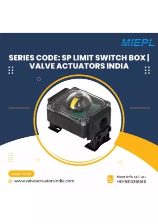
SP - SM limit switch box series Compact limit switch box for industrial, water treatment and light duty applications. Features • Integrated mounting kit for NAMUR pattern • Corrosion free glass reinforced plastic enclosure on SP series • Nickel plated aluminium body on SM series • 1 cable entry (SP) or 2 cable entries (SM) either metric or imperial • Multiple indicator options • Easy wiring through the terminal PCB board Approvals ATEX, EAC, CCOE: Ex II 2GD Ex ia IIC T4/T5/T6 Ex ia IIIB T44 °C.......T108 °C Db IP6* Ta: -20 °C < Ta < 80 °C SIL certificate: Up to SIL 2 certified by TUV Protection rating: IP 65 IP 67 on request Nema 4 4X on request Temperature: -20 to +80 °C (-4 to +176 °F) standard temperature range C€ © atex [B[ SIL/ SP limit switch box SM limit switch box 80 mm [3 1/8 in] 130 mm [5 1/8 in] f i Limit Switch Boxes 20
SP - SM limit switch box series Nomenclature SP N1 2 H 0 - D H W 0 0 R 1 Box SP = Glass reinforced plastic body with polycarbonate cover SM = Aluminium body with polycarbonate cover Switch 01= SPDT el.mech. switch silver plated contacts 03= SPDT el.mech. switch gold plated contacts (for Ex'ia') 1F = DPDT el.mech. switch silver plated contacts C4 = SPDT magnetic hermetically sealed reed switch (for Ex'ia' low temperature) N1 = SPDT magnetic hermetically sealed silver plated snap acting contacts N3 = SPDT magnetic hermetically sealed gold plated snap acting contacts (for Ex'ia') 70 = Inductive proximity NAMUR sensor NJ2-V3-N 2 wire NC logic (for Ex'ia') 73 = Inductive proximity sensor model NBB2-V3-E2, 3 wire PNP NO See additional information and options on pages 14-19 Terminals A = Screw type terminals 4 = Blue screw terminals (for Ex'ia') 0 = Screw terminals with sov connection 2 = Blue screw terminals with sov connection (for Ex'ia') Coating 0 = Black plastic enclosure (on SP series) N = Nickel plated aluminium body (on SM series) Cable Entries D = 1 cable entry 1/2" NPT E = 1 cable entry M20 x 1.5 1 = 2 cable entries 1/2" NPT (SM series only) 2 = 2 cable entries M20 x 1.5 (SM series only) Approval W = Weather proof A = ATEX certified G = EAC certification for Russian market See additional information and options on page 13 Marking 0 = Standard location 1 = Intrinsically safe certification See additional information and options on page 13 IP Protection rating 0 = Weather proof IP65 7 = Nema 4 and 4X 2 = Weather proof IP67 Temperature A = Ambient temperature range: -20 to +80 °C (-4 to +176 °F) B = Ambient temperature range: -20 to +70 °C (-4 to +158 °F) for sensor option 73 Material 1 = Glass reinforced plastic body and polycarbonate cover (on SP series) 2 = Nickel plated aluminium body and polycarbonate cover (on SM series) Keeping the World Flowing 21
SF - SS - SB limit switch box series Multi purpose limit switch box for safe area or Intrinsically Safe applications. Features • Twin shaft design • Self lubricating bushings • Copper free aluminium or 316 stainless steel housing option for maximum corrosion protection • 2 cable entries either metric or imperial • Multiple indicator options • Easy wiring through the terminal PCB board • Position transmitter board optional • Suitable for arctic environments Approvals ATEX, lECEx, EAC, CCOE: SF-SS series (ATEX & IECEx) SB series (ATEX only) Ex II 1GD Ex ia IIC T4...T6 Ga Ex II 2GD Ex ia IIC T6...T4 Gb Ex ia IIIC T95°C...T120°C Da Ex ia IIIB T44°C...T108° -60°C<Ta<+105°C UL: Class I Division 2 Groups A, B, C, D Class II Division 2 Groups F, G SIL certificate: Up to SIL 3 certified by TUV Protection rating: IP 66 / 67 Nema 4 4X on request Temperature: -20 to +80 °C (-4 to +176 °F) standard temperature range -60 to +105 °C (-76 to +221 °F) available on request S C6© ATEX ER[ SILf PESO SF limit switch box 0 50 [ 0 1,969 in] M6X1-6H SS limit switch box 33 [1,299 in] I l~l | 40 [1,575 in] r-1 SB limit switch box f i Limit Switch Boxes 22
SF - SS - SB limit switch box series Box SB = Aluminium body with polycarbonate cover SF = Aluminium enclosure SS = 316 stainless steel enclosure Switch 01 = SPDT el.mech. switch silver plated contacts 03= SPDT el.mech. switch gold plated contacts (for Ex'ia') 1F = DPDT el.mech. switch silver plated contacts C4 = SPDT magnetic hermetically sealed reed switch (for Ex'ia' low temperature) C8 = DPDT magnetic hermetically sealed reed switch (for Ex'ia' low temperature) N1 = SPDT magnetic hermetically sealed silver plated snap acting contacts N3 = SPDT magnetic hermetically sealed gold plated snap acting contacts N4 = DPDT magnetic hermetically sealed silver plated snap acting contacts 62 = Inductive proximity NAMUR sensor SJ3,5-SN 2 wire NC logic (for Ex'ia' low temperature safety function) 70 = Inductive proximity NAMUR sensor NJ2-V3-N 2 wire NC logic (for Ex'ia') 73 = Inductive proximity sensor model NBB2-V3-E2, 3 wire PNP NO, 10-30 VDC, 0-100 mA 86 = Inductive proximity NAMUR sensor model NJ4-12GK-SN 2 wire NC logic (for Ex'ia' safety function) T0 = 4-20 mA position transmitter H0 = 4-20 mA HART position transmitter Atex Ex ia IIC T6 / T4 certified See additional information and options on pages 14-19 Switch Quantity 2 = 2 switches 3 = 3 switches Terminals 0 = Screw terminals with extra poles for solenoid valve connection 2 = Blue screw type terminals with extra poles for sov connection (for Ex'ia') A = Screw terminal strip 8 = Blue cage clamp terminals (for low temperature and switch codes 62, 63, H0) E = Cage clamp terminals (for low temperature) Coating 0 = Black powder coating 1 = Blue powder coating E = Electro polished finishing (on SS series) Cable Entries 1 = 2 cable entries 1/2" NPT 2 = 2 cable entries M20 x 1.5p Visual Position Indicator 0 = 3D plastic visual position indicator red and green 1 = No visual position indicator T = 3D stainless steel position indicator See additional information and options on page 11 Approval W = Weather proof X = ATEX and IECEx certified box A = ATEX certified box B = ATEX certified box and SIL2 approval C = ATEX certified box and SIL3 approval G = EAC certification for Russian market J = CCOE certification for Indian market U = UL certified box * SIL2 / SIL3 options available on request See additional information and options on page 13 Marking 0 = Standard location 1 = Instrinsically safe certification 9 = cULus Class 1/2 Div 2 (with switches code: C4, C8, N1, N3) See additional information and options on page 13 IP Protection rating 1 = Weather proof IP66 / IP67 7 = NEMA 4 and 4X Temperature A = Ambient temperature range: -20 to +80 °C (-4 to +176 °F) L = Ambient temperature range: -40 to +80 °C (-40 to +176 °F) P = Ambient temperature range: -60 to +80 °C (-76 to +176 °F) for switch code C4 U = Ambient temperature range: -20 to +40 °C (-4 to +104 °F) B = Ambient temperature range: -20 to +70 °C (-4 to +158 °F) Material 2 = Die-cast aluminium heavy duty body and polycarbonate cover (on SB series) 4 = Copper free aluminium (on SF series) 6 = 316 stainless steel heavy duty enclosure (on SS series) >] Keeping the World Flowing 23
HW limit switch box series Control unit that combines a limit switch box and solenoid valve into a single device. Maximum efficiency with minimum customer effort. Features • Easy wiring through the terminal PCB board • Optional position transmitter boards • Optional Profibus communication board for complete process handling Approvals EAC, UL general purpose SIL certificate: Up to SIL 2 approval on request Protection rating: IP66 / 67 Nema 4 4X on request Temperature: -60 to +105 °C (-76 to +221 °F) standard temperature range • Twin shaft design • Self lubricating bushings • Optional integrated solenoid valve for maximum efficiency and compactness • 3 or 5 way pneumatic valve with single or double coil configurations • Aluminium enclosure with thick powder coat paint and integrated NAMUR mounting kit • Up to 3 cable entries either metric or imperial • Multiple indicator options SIL SIL LEVEL 2 HW limit switch box 6 [0,236 in] f i Limit Switch Boxes 24
HW limit switch box series Nomenclature HW N1 2 2 2 - 3 T W 9 7 P 3 0 A Box HW = Aluminium control unit enclosure Switch 01= SPDT electromechanical switches, silver plated contacts 03 = SPDT electromechanical switches, gold plated contacts 1F = DPDT electromechanical switches silver plated contacts 70 = NAMUR inductive proximity sensor P+F type NJ2-V3-N, NAMUR NC 2 wire (for Ex'ia') 73 = Inductive proximity P+F NBB2-V3-E2, 3 wire PNP NO C4 = Magnetic SPDT hermetically sealed switch (suitable for Ex'ia') C8 = Magnetic DPDT hermetically sealed switch (suitable for Ex'ia') N1 = Magnetic proximity SPDT hermetically sealed switch, silver plated snap acting contacts N3 = Magnetic proximity SPDT hermetically sealed switch, gold plated snap acting contacts N4 = Magnetic proximity DPDT hermetically sealed switch, silver plated snap acting contacts DB =3 position control system for single acting actuators, 5/3 way, double coil sov DA =3 position control system for double acting actuators, 5/3 way, double coil sov A1 = Asi board with 2 SPDT switches and solenoid valve control T0 = 4-20 mA analog position transmitter H0 = 4-20 mA HART transmitter Exia IIC certified PG = Profibus communication board See additional information and options on pages 14-19 Switch Quantity 0 = No switches for digital limit position feedback 1 = 1 switch or sensor (for DB, DA switch options) 2=2 switches or sensors 3=3 switches or sensors 4 = 4 switches or sensors Cable Entries 1 = 2 cable entries 1/2" NPT 2 =2 cable entries M20x1.5 3 =2 x 1/2" NPT + 1 x 3/4" NPT cable entries 4 = 2 x M20 x 1.5p + 1 x M25 x 1.5p cable entries Visual Position Indicator 0 = Red and green visual position indicator See additional information and options on page 11 Approval W = Weather proof limit switch box G = EAC certified box for Russian market, with RTN permit U = UL certified box See additional information and options on page 13 Marking 0 = Ordinary location A = CULUS normally location See additional information and options on page 13 IP Protection rating 1 = Weather proof IP66/IP67 7 = Nema 4 4X Temperature S = Ambient temperature range: -10 to +50 °C (+14 to +122 °F) 7 = Ambient temperature range: -10 to +40 °C (+14 to +104 °F) 5 = Ambient temperature range: -5 to +50 °C (+23 to +122 °F) A = Ambient temperature range: -20 to +80 °C (-4 to +176 °F) without solenoid valve Material and solenoid valve selection 3 = Aluminium heavy duty body and cover A = Aluminium heavy duty body and cover die-cromated, 5/2 way aluminium solenoid valve, single coil B = Aluminium heavy duty body and cover die-cromated, 5/2 way aluminium solenoid valve, double coil C = Aluminium heavy duty body and cover die-cromated, 5/3 way aluminium solenoid valve, blocked centre, double coil (DB switch option) D = Aluminium heavy duty body and cover die-cromated, 5/3 way aluminium solenoid valve, exhaust centre, double coil (DA switch option) Coil Rating 0 = No solenoid valve available 2 = Coil rating: 12 VDC 2, 3 W 3 = Coil rating: 24 VDC 2, 3 W 4 = Coil rating: 24 VAC 2, 8 VA 5 = Coil rating: 110 VAC 2, 8 VA 6 = Coil rating: 230 VAC 2, 8 VA 1 = Ex'ia' certified pilot valve coil rating: 6 VDC 7 = Ex'ia' certified pilot valve coil rating: 12 VDC 8 = Ex'ia' certified pilot valve coil rating: 24 VDC 9 = Ex'n' certified pilot valve coil rating: 24 VDC A = Ex'n' certified pilot valve coil rating: 110 VAC Pneumatical Connection 0 = No pneumatic connections A = 1A" NPT/F pneumatical connections >] Keeping the World Flowing 25
SK - SQ limit switch box series Compact limit switch box for hazardous areas, with explosionproof protection method. Features • Twin shaft design • Metallic self lubricant bushings • Aluminium or 316L stainless steel housing option for maximum corrosion protection • 2 cable entries either metric or imperial • Adjustable mounting kit for NAMUR actuators available on request • Easy wiring through the terminal PCB board • Suitable for arctic environments Approvals ATEX, lECEx, EAC, CCOE, INMETROL: Ex II 2GD Ex db IIC T4/T5/T6 Gb Ex tb IIIC T135/T100/T85°C Db Ta: -55 °C < Ta < 105 °C / 80 °C / 60 °C UL (available on Sk series only): Class I Division 1 Groups A, B, C, D Division 2 Groups A, B, C, D Class II Division 1 Groups E, F, G Division 2 Groups F, G SIL certificate: Up to SIL 3 certified by TUV Protection rating: IP 66 / 67 IP 66 / 68 15 m for 100 hours Nema 4 4X on request Temperature: -20 to +80 °C (-4 to +176 °F) standard temperature range -55 to +105 °C (67 to +221 °F) available on request S « Q atex [fj[ SILX peso SK limit switch box 0 50 [0 1,969 in] ISO F05 M6X1 - 6H SQ limit switch box Optional adjustable mounting kit for NAMUR actuators f i Limit Switch Boxes 26
SK - SQ limit switch box series Nomenclature SK N1 2 0 0 - 1 1 X 2 1 A 3 Box SK = Die-cast aluminium enclosure SQ = 316L stainless steel enclosure Switch 01 = SPDT el.mech. switch silver plated contacts 03 = SPDT el.mech. switch gold plated contacts 1F = DPDT el.mech. switch silver plated contacts C4 = SPDT magnetic hermetically sealed reed switch N1 = SPDT magnetic hermetically sealed silver plated snap acting contacts N3 = SPDT magnetic hermetically sealed gold plated snap acting contacts 73 = Inductive proximity sensor model NBB2-V3-E2, 3 wire PNP NO See additional information and options on pages 14-19 Switch Quantity 2 = 2 switches Terminals 0 = Screw type terminals with sov connection E = Cage clamp terminals with sov connection (for low temp.) Coating 0 = Black powder coating (SK Series) Aluminium E = Electro polish finishing (SQ Series) Stainless Steel Cable Entries 1 = 2 cable entries 1/2" NPT 2=2 cable entries M20 x 1.5 Visual Position Indicator 0 = 3D plastic visual position indicator red and green T = 3D stainless steel position indicator See additional information and options on page 11 Approval X = ATEX and IECEx certified box D = ATEX and IECEx certified box with SIL2 approval E = ATEX and IECEx certified box with SIL3 approval G = EAC certification for Russian market 1 = INMETRO certification for Brazilian market N = NEPSI certification for Chinese market J = CCOE certification for Indian market U = UL certified box (only for SK series) W = Weather proof * SIL2 / SIL3 options available on request See additional information and options on page 13 Marking 0 = Standard location 2 = Certification marking: Ex II 2GD Exd IIC 7 = cULus Class 1/2 Div1 (only for SK series) 8 = cULus Class 1/2 Div 1/2 with switches code: C4, N1, N3. (Only for SK series) See additional information and options on page 13 IP Protection rating 1 = Weather proof IP66/IP67 3 = Weather proof IP66/IP68 7 = Nema 4 and 4X Temperature A = Ambient temperature range: -20 to +80 °C (-4 to +176 °F) L = Ambient temperature range: -40 to +80 °C (-40 to +176 °F) N = Ambient temperature range: -55 to +80 °C (-67 to +176 °F) for switch code C4 Material 3 = Die-cast aluminium heavy duty body and cover (on SK series) 7 = 316L Stainless steel heavy duty enclosure (on SQ series) Note: Optional mounting kit for NAMUR actuators ordering code: KN07 >] Keeping the World Flowing 27
SY - SW limit switch box series Limit switch box for heavy duty explosionproof applications in the oil & gas and petrochemical industries, both on-shore and off-shore. Features • Twin shaft design • Metallic self lubricating bushings • Copper free aluminium or 316 stainless steel housing option for maximum corrosion protection • Up to 4 cable entries either metric or imperial • Multiple indicator options • Easy wiring through the terminal PCB board • High volume for the maximum wiring comfort • Optional position transmitter board • Suitable for artic environments Approvals ATEX, lECEx, EAC, CCOE, INMETRO, NEPSI: Ex II 2GD Ex db IIC T4/T5/T6 Gb Ex tb IIIC T140/T110/T110°C Db Ta: -60 °C < Ta < 105 °C / 80 °C / 60 °C UL: Class I Division 1 Groups B,C,D Division 2 Groups A, B, C, D Class II Division 1 Groups E,F,G Division 2 Groups F, G SIL certificate: Up to SIL 3 certified by TUV Protection rating: IP 66 / 68 10 m for 48 hours Nema 4 4X on request Temperature: -20 to +80 °C (-4 to +176 °F) as standard temperature range -60 to +105 °C (-76 to +221 °F) available on request ® C€ €> atex ER[ SIL/ peso & J, SY limit switch box SW limit switch box f i Limit Switch Boxes 28
SY - SW limit switch box series Box SY = Copper free aluminium enclosure SW = Stainless steel 316 enclosure Switch 01 = SPDT electro-mechanical switch silver plated contacts 1F = DPDT electro-mechanical switch silver plated contacts C4 = SPDT magnetic hermetically sealed reed switch C8 = DPDT magnetic hermetically sealed reed switch N1 = SPDT magnetic hermetically sealed silver plated snap acting contacts N4 = DPDT magnetic hermetically sealed silver plated snap acting contacts 32 = Inductive proximity sensor model NBN4-12GM40-Z0 2 wire 73 = Inductive proximity sensor model NBB2-V3-E2, 3 wire PNP NO T0 = 4-20 mA position transmitter H0 = 4-20 mA HART position transmitter Atex EEx ia IIC T6 / T4 certified P0 = Partial Stroke Test device with either remote or local magnetic key activation See additional information and options on pages 14-19 Switch Quantity 2 = 2 switches 4 = 4 switches 6=6 switches Terminals 0 = Screw type terminals with sov connection A = Screw type terminals E = Cage clamp terminals with sov connection (for low temperature) D = Cage clamp terminals (for low temperature) Coating 0 = Black powder coating (SY Series) E = Electro polish finishing (SW Series) Cable Entries 1 = 2 cable entries 1/2" NPT 2=2 cable entries M20 x 1.5p T =4 cable entries 1/2" NPT U = 4 cable entries M20 x 1.5p Visual Position Indicator 0 = 3D plastic visual position indicator red and green 2 = 3-position indicator (T-port 180 deg. Blocked centre) A = 3-position indicator (L-port) B = 3-position indicator (T-port 180 deg.) T = 3D stainless steel position indicator See additional information and options on page 11 Approval X = ATEX and lECEx certified box D = ATEX and lECEx certified box with SIL2 approval E = ATEX and lECEx certified box with SIL3 approval G = EAC certification for Russian market 1 = INMETRO certification for Brazilian market N = NEPSI certification for Chinese market J = CCOE certification for Indian market U = UL certified box W = Weather proof * SIL2 / SIL3 options available on request See additional information and options on page 13 Marking 0 = Standard location 2 = Certification marking: Ex II 2GD Exd IIC 7 = cULus Class 1/2 Div1 8 = cULus Class 1/2 Div 1/2 with (with switches code: C4,C8,N1,N3) See additional information and options on page 13 IP Protection rating 3 = Weather proof IP66 / IP68 7 = Nema 4 and 4X Temperature A = Ambient temperature range: -20 to + 80 °C (-4 to +176 °F) L = Ambient temperature range: -40 to + 80 °C (-40 to +176 °F) P = Ambient temperature range: -60 to + 80 °C (-76 to +176 °F) for switch codes C4 and C8 Material 4 = Copper free aluminium heavy duty body and cover (SY series) 6 = 316 stainless steel heavy duty enclosure (SW series) >] Keeping the World Flowing 29
SX - SH limit switch box series Limit switch box designed for explosionproof applications. Features • Twin shaft design • Metallic self lubricating bushings • Aluminium enclosure with thick protective powder coating • Up to 3 cable entries either metric or imperial • Multiple indicator options • Easy wiring through the terminal PCB board Approvals ATEX, lECEx, EAC, CCOE, INMETRO: Ex II 2GD Ex db IIB T4/T5/T6 Gb (SX series) Ex II 2GD Ex db IIB + H2 T4/T5/T6 Gb (SH series) Ex tb IIIC T135/T100/T85°C Db Ta: -20 °C < Ta < 105 °C / 75 °C / 60 °C UL: Class I Division 1 Groups C, D Division 2 Groups A, B, C, D Class II Division 1 Groups E, F, G Division 2 Groups F, G SIL certificate: Up to SIL 3 certified by TUV Protection rating: IP 66 / 67 Nema 4 4X on request Temperature: -20 to +80 °C (-4 to +176 °F) standard temperature range S « Q atex [R[ SIL/ peso SX limit switch box 85 mm f i Limit Switch Boxes 30
SX - SH limit switch box series Nomenclature SX N1 2 0 0 - 1 0 X 3 2 A 4 Box SX = Exd IIB applications SH = Exd IIB+H2 applications Switch 01 = SPDT elec.mech. switch silver plated contacts 1F = DPDT elec.mech. switch silver plated contacts C4 = SPDT magnetic hermetically sealed reed switch C8 = DPDT magnetic hermetically sealed reed switch N1 = SPDT magnetic hermetically sealed silver plated snap acting contacts N4 = DPDT magnetic hermetically sealed silver plated snap acting contacts 32 = Inductive proximity sensor model NBN4-12GM40-Z0 2 wire 73 = Inductive proximity sensor model NBB2-V3-E2, 3 wire PNP NO T0 = 4-20 mA position transmitter H0 = 4-20 mA HART position transmitter Atex EEx ia IIC T6 / T4 certified P0 = Partial Stroke Test device with magnetic key See additional information and options on pages 14-19 Switch Quantity 2 =2 switches 4=4 switches (on Exd IIB certification) Terminals 0 = Screw type terminals with sov connection A = Screw type terminals E = Cage clamp terminals with sov connection (for low temperature) D = Cage clamp terminals (for low temperature) Coating 0 = Black powder coating Cable Entries 1 = 2 cable entries 1/2" NPT 2=2 cable entries M20x1.5 3 = 2 x 1/2"NPT + 1 x 3/4"NPT cable entries Visual Position Indicator 0 = 3D plastic visual position indicator red and green 2 = 3-position indicator (T-port 180 deg. Blocked centre) A = 3-position indicator (L-port) B = 3-position indicator (T-port 180 deg.) T = 3D stainless steel position indicator See additional information and options on page 11 Approval X = ATEX and IECEx certified box D = ATEX and IECEx certified box with SIL2 approval E = ATEX and IECEx certified box with SIL3 approval G = EAC certification for Russian market 1 = INMETRO certification for Brazilian market N = NEPSI certification for Chinese market J = CCOE certification for Indian market U = UL certified box W = Weather proof * SIL2 / SIL3 options available on request See additional information and options on page 13 Marking 0 = Standard location 3 = Certification marking: Ex II 2GD Exd IIB 4 = Certification marking: Ex II 2GD Exd IIB + H2 7 = cULus Class1/2 Div 1 8 = cULusClass 1/2 Div 1/2 (with switches code: C4, C8, N1, N3) See additional information and options on page 13 IP Protection rating 1 = Weather proof IP 66/67 7 = Nema 4 and 4X Temperature A = Ambient temperature -20 to + 80 °C (-4 to +176 °F) E = -25 to +80°C (-13 to +176 °F) UL approval only Material 3 = Die cromated aluminium heavy duty body and cover >] Keeping the World Flowing 31
BM - TB limit switch box series Limit switches for hazardous areas with Exd or Exia protection methods. Designed for linear valves and general purpose applications. Features • AISI 316 stainless steel rugged BM series enclosure • Standard 450 mm flying leads • Stainless steel or aluminium materials for optional junction box with TB series • Magnetic or ferrous sensing capabilities • Subsea application on request, tested up to 300 bar • Optional subsea cable and connector for underwater link Approvals ATEX, EAC, INMETRO: Ex II 2GD Ex d IIC T6/T5/T4 Gb Ex tb IIIC T80°C/T95°C/T115°C Db ATEX, IECEx Ex II 1GD Exia IIC T4 Ga Exia IIIC T135°C Da Ta = -40 °C < Ta < 90 °C UL: only available on BMC4 Class I, Division 1 and 2, Groups A, B, C and D Class II, Division 1 Groups E, F and G Class II Division 2, Groups F and G SIL certificate: Up to SIL 3 approval on request Protection rating: BM: IP66 / 68 TB: IP67 / 68 Nema 4 4X on request ® ce © atex er[ siLv BM dimensional drawing 25 [0,984 in] ^ 17 [0,669 in] 59 [2,323 in] 107 [4,213 in] TB limit switch box f i Limit Switch Boxes 32
BM - TB limit switch box series Nomenclature BM N1 1 1 E - E 1 A 2 3 A 6 Box BM = Proximity bolt switch TB = Proximity bolt switch with integrated junction box Switch C4 = Magnetic SPDT hermetically sealed switch (suitable for Ex'ia') N1 = Magnetic proximity SPDT hermetically sealed switch, silver plated snap acting contacts Switch Quantity 1 = 1 switch or sensor 2 =2 switches (for TB series only) Terminals A = Screw type terminals (for TB series) 1 = Flying leads (for BM series) Coating 0 = Black polyester powder coating (for aluminium TB series) E = Stainless steel finishing Cable Entries 1 =2 x 1/2" NPT cable entries (for TB series with 2 switches) 2 =2 x M20 x 1.5p cable entries (for TB series with 2 switches) E =1 x M20 x 1.5p cable entry D =1 x 1/2" NPT cable entry Visual Position Indicator 1 = No visual position indicator 6 = LED Indicator (available for UL approval only) Approval* W = Weather proof limit switch box A = ATEX certified box G = EAC certified box for Russian market, with RTN permit U = UL certified box (available on BMC4 option) X = ATEX lECEx certification See additional information and options on page 13 Marking 0 = Standard location 1 = Certification marking: Ex II 2 GD Exia IIC (available for C4 switch option) 2 = Certification marking: Ex II 2GD Exd IIC 7 = CULUS Class1/2 Div1 (available on BMC4 option) 8 = CULUS Class1/2 Div 1/2 (available on BMc4 option) See additional information and options on page 13 IP Protection rating 2 = Weather Proof 67 (available on TB series) 3 = Weather Proof IP66/68 (available on BM series) 6 = Subsea application up to -40 meters (available on BM series)** 7 = Nema 4 4X (available on BMC4 option) Temperature A = Ambient temperature range: -20 to +80 °C (-4 to +176 °F) L = Ambient temperature range: -40 to +80 °C (-40 to +176 °F) Material 6 = 316 stainless steel heavy duty enclosure 8 = 316 stainless steel with aluminium junction box (only for TB series) 3 = Aluminium (available for UL approval only) * SIL2 and SIL3 available on request ** Subsea cable with fast connector with standard length as follow: 5, 20, 40 mt Sensing Distance Chart Notes: PI: Is the point where the switch first operates. DO: Is the point where the switch is released. PI & DO values refers to the distance between the 2 axis of BOLT switch and target. Target distance refers to the distance between the 2 opposite faces of BOLT switch and target. For BMN1 switch the maximum operating distance is 2 mm using a properly size ferrous target. This distance may be increased using a magnetic target (optional). BMC4 switch is supplied with its standard magnetic target. Optional magnetic target to increase the sensing range of the switch are available. For any kind of request please contact SOLDO. Keeping the World Flowing 33
ES Easy limit switch box Limit switch box created and engineered for manual valve application in explosionproof environments. Features • Proximity non-contact design • Easy to install and simple to maintain • Copper free aluminium or 316 stainless steel housing option for maximum corrosion protection • Single or double cable entries options either metric or imperial • Easy wiring through terminal PCB board • Suitable for artic environments Approvals ATEX, lECEx, EAC, INMETRO: Ex II 2GD Ex db IIC T6/T5/T4 Gb Ex tb IIIC T85/T100/T120 °C Db Ta = -65 °C < Ta < 105 °C UL: Class I, Division 1 and 2, Groups A, B, C and D Class II, Division 1 Groups E, F and G Class II Division 2, Groups F and G SIL certificate: Up to SIL 2 approval on request Protection rating: IP66 / 67 IP66 / 68 15 m for 70 hours Nema 4 4X on request ® ce © atex er[ SIL/ ES Easy limit switch box MAGNET CARRIER 11.5 [0 45] f i Limit Switch Boxes 34
ES Easy limit switch box Nomenclature ES N1 2 0 0 - 1 1 X 2 1 A 4 Box ES = Manual valve magnetic switch box Switch N1 = Snap acting, hermetically sealed, silver contacts SPDT switch, rating max N3 = Snap acting, hermetically sealed, gold contacts SPDT switch, rating max C4 = Inert gas hermetically sealed, rhodium contacts SPDT switch, rating max See additional information and options on pages 14-19 Switch Quantity 2 = Quantity of switch Terminals 0 = Screw Terminal Strips Coating 0 = Black powder coating E = Electro polish finishing Cable Entries 1 =2 x 1/2" NPT cable entries 2 =2 x M20 x 1.5p cable entries D =1 x 1/2" NPT cable entry (standard option) E =1 x M20 x 1.5p cable entry Approval U = UL certification S = UL certification with SIL2 approval X = ATEX and lECEx certification D = ATEX and lECEx certification with SIL2 approval See additional information and options on page 13 Marking 2 = Certification marking: Ex II 2GD Exd IIC See additional information and options on page 13 IP Protection rating 1 = IP66 / 67 (standard option) 2 = IP66 / 68 15 m for 70 hours Temperature A = Ambient temperature range: -20 to + 80 °C (-4 to +176 °F) standard L = Ambient temperature range: -40 to + 80 °C (-40 to +176 °F) P = Ambient temperature range: -60 to + 80 °C (-76 to +176 °F) for switch code C4 Material 4 = Copper free aluminium body and cover 6 = 316 stainless steel body and cover >] Keeping the World Flowing 35
Mounting Kits The Rotork Instruments KN and KNC mounting kit series have been designed to mount almost any device on a NAMUR pattern actuator. KN and KNC mounting kits are made from AISI 304 stainless steel to provide a reliable solution to install your ISO F05 drilled device to complete the automated valve package. Mounting kit dedicated to all Soldo limit switch box series (excluding SP, SM series) Adjustable mounting kit dedicated to SK and SQ series only f i Limit Switch Boxes 36
Mounting Kits Linear Mounting Kit Linear diaphragm and piston actuators have always been problematic to mount, often requiring external switches to indicate position, therefore losing the flexibility and benefits of a limit switch box. With the new linear universal mounting kit, Rotork Instruments provides a proven system to fit every limit switch box in our range to a linear valve from 20 up to 250 mm stroke with two different kit layouts: 20-150 mm stroke; 100-250 mm stroke. The mounting kit includes a specific position dome indicator, perfectly showing the open/close position status. The graduated lever system, combined with the remote pin connection, offers great flexibility to fit a huge variety of systems and offers precise adjustment on the go. Actuator Mount Patterns Compatibility Keeping the World Flowing 37
Appendix A: Equipment Certification Requirements for Hazardous Locations ATEX & lECEx cCS Aus Typical ATEX & lECEx Marking [*ATEX only] Typical North American Marking (CSA) CL, ® t. \ ..t Class I, Division 1, Groups A,B,C,D T4 ft ft II t 'Equipment Group 2 G t Environment Class II, Division 1, Groups E,F,G *Equipment Category T4 Gb ! t Temperature Equipment Class (T1-T6) Protection Level (EPL) T135°C Db t ! Temperature Equipment Class (°C) Protection Level t t t Explosion Type of Gas Protection Protection Group Class I t Hazard Class AEx ia IIC T4 t t Zone 0, t Area Classification Ex tb IIIC I t t Protection Temperature Concept Class Code Approved to Gas US Standards Group Protection Concepts Protection Concepts f i Limit Switch Boxes 38
Appendix A: Equipment Certification Requirements for Hazardous Locations ATEX & lECEx Certificate Number Temperature Classification Classification of maximum surface temperatures for Group II Electronic Equipment (T Class). 700° °C 600° EC-type examination \—500° | -d 450° — 400° — 300° -d 300° IECEx t Name of Notified Body performing EC-type examination CSA t Name of Body Performing IECEx Certification 13.1234 t Serial Number Year of Certification Suffixes: U - component certification X - special conditions for safe use apply — 200°-0200° -0135° Apparatus Groups [ATEX and IECEx] d 100° —100" 85° A Dusts Typical Ignition Temperatures Apparatus Groups (US / CAN) Ingress Protection Codes Enclosure Type Ratings (NEMA / CSA / UL) Classification of Divisions and Zones * On occasion the ATEX and IEC Zones may be used in the corresponding NEC and CEC system Keeping the World Flowing 39
■■ _ ® rotorif Keeping the World Flowing www.rotork.com A full listing of our worldwide sales and service network is available on our website. Rotork plc Brassmill Lane, Bath, UK tel +44 (0)1225 733200 fax +44 (0)1225 333467 emailmail@rotork.com Rotork is a corporate member of the Institute of Asset Management As part of a process of on-going product development, Rotork reserves the right to amend and change specifications without prior notice. Published data may be subject to change. For the very latest version release, visit our website at www.rotork.com The name Rotork is a registered trademark. Rotork recognises all registered trademarks. Published and produced in the UK by Rotork Controls Limited. POWJB0518 PUB109-003-00 Issue 05/18