Chapter 8 Single-bit Instructions and Programming
Chapter 8 Single-bit Instructions and Programming. Objective. 8051 有一個很特殊且 powerful 的功能:8051 允許 programmer 每次只存取一個 bit ( 而非一個 byte) 的方式,使用在 RAM 中或 register 的資料 。 這樣的方式,稱為 bit-addressable。 只有在 RAM 中某些特定的位址,或是某些特定的 registers ,提供 bit-addressable 的功能。

Chapter 8 Single-bit Instructions and Programming
E N D
Presentation Transcript
Objective • 8051 有一個很特殊且 powerful 的功能:8051 允許 programmer 每次只存取一個 bit (而非一個 byte) 的方式,使用在 RAM 中或 register 的資料。這樣的方式,稱為 bit-addressable。 • 只有在RAM 中某些特定的位址,或是某些特定的 registers,提供 bit-addressable 的功能。 • 相對的, 8051 也提供一些特殊的指令,專門用來對一個 bit 做存取或運算。 • 這章節中就是要去了解這些關於 bit-addressable 指令的用法。
Sections 8.1 Single-bit Instruction Programming 8.2 Single-bit Operations with CY 8.3 Reading Input Pins vs. Port Latch
Bit-addressability (1/2) • In most microprocessors, data is accessed in byte-sized chunks. • However, in many applications we need to change one bit, for example, to turn on or off a device. • The bit-addressability of the 8051 • The ability to access data in single bit instead of the whole byte. • Make 8051 become one of the most powerful 8-bit microprocessors.
Bit-addressability (2/2) • Which portions of the microprocessor, I/O ports, registers, RAM, or ROM are bit-addressable? • ROM holds program code for executions. There is no need for bit-addressability. • I/O: all ports are bit-addressable • Register: some of them are bit-addressable • RAM: bit-addressable RAM (20H-3FH)
I/O Ports and Bit-addressability • We can access either the entire 8 bits or any single bit without altering the rest. • Example: SETB P2.3 ;set pin 3 of P2 to high (1) CLR P1.0 ;clear pin 0 of P1(0) • Remember that D0 is the LSB and D7 is the MSB.
8051 P1.0 Example 8-1 (a-1) Write the following program. • Create a square wave of 50% duty cycle on bit 0 of port 1. Solution: The 50% duty cycle means that the period of “on” state is 50% in the period of the whole pulse (“on” state pluses “off” state). That is, the “on” and “off” state have the same length. on state high portion off state low portion 50% 50% whole pulse
Example 8-1 (a-2) • Create a square wave of 50% duty cycle on bit 0 of port 1. HERE:SETB P1.0 ;set to high bit 0 of port 1 LCALL DELAY ;call the delay subroutine CLR P1.0 ;P1.0=0 LCALL DELAY SJMP HERE Another way to write the above program is: HERE:CPL P1.0 ;complement bit 0 of port 1 LCALL DELAY ;call the delay subroutine SJMP HERE
8051 P1.3 Example 8-1 (b-1) Write the following programs. (b) Create a square wave of 66% duty cycle on bit 3 of port 1. Solution: The 66% duty cycle means that the period of “on” state is 66% in the period of the whole pulse. That is the “on” state is twice the “off” state. 66% 34%
Example 8-1 (b-2) (b) Create a square wave of 66% duty cycle on bit 3 of port 1. BACK:SETB P1.3 ;set port 1 bit 3 high LCALL DELAY LACLL DELAY CLR P1.3 ;clear bit 2 of port 1 LACLL DELAY SJMP BACK
Bit Address of I/O Ports • Each port has its byte address. • Ex: P0 has address 80H. • Each pin of port has its bit address. • Ex: pin 7 of port 0 has bit address 87H • Note that pin 0 of port 0 has address 80H. Your instruction decides that the operand is bit or byte. • The bit address of ports • See Table 8-2 • See Figure 8-1 or Figure A-1 for SFR RAM address
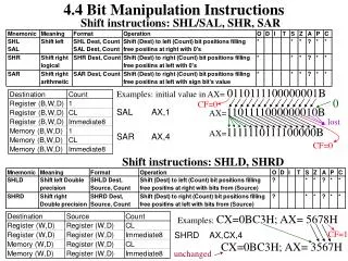
FF F0 F7 F6 F5 F4 F3 F2 F1 F0 B E0 E7 E6 E5 E4 E3 E2 E1 E0 ACC D0 D7 D6 D5 D4 D3 D2 D1 D0 PSW B8 -- -- -- BC BB BA B9 B8 IP B0 B7 B6 B5 B4 B3 B2 B1 B0 P3 A8 AF -- -- AC AB AA A9 A8 IE A0 A7 A6 A5 A4 A3 A2 A1 A0 P2 Figure 8-1. SFR RAM Address (Byte and Bit) (1/2) Special Function Registers Byte address Bit address
99 SBUF not bit addressable 98 9F 9E 9D 9C 9B 9A 99 98 SCON 97 96 95 94 93 92 91 90 90 P1 not bit addressable TH1 8D 8C TH0 not bit addressable 8B not bit addressable TL1 not bit addressable TL0 8A not bit addressable 89 TMOD D7 D6 D5 D4 D3 D2 D1 D0 88 TCON PCON 87 not bit addressable not bit addressable DPH 83 82 DPL not bit addressable SP not bit addressable 81 A7 A6 A5 A4 A3 A2 A1 A0 80 P0 Special Function Registers Figure 8-1. SFR RAM Address (Byte and Bit) (2/2)
Example 8-2 For each of the following instructions, state which bit of which SFR will be affected. Use Figure 8-1. (a) SETB 86H (b) CLR 87H (c) SETB 92H (d) SETB 0A7H (e) CLR 0F2H (f) SETB 0E7H Solution: (a) SETB 86H is for SETB P0.6 (b) CLR 87H is for CLR P0.7 (c) SETB 92H is for SETB P1.2 (d) SETB 0A7H is for SETB P2.7 (e) CLR 0F2H is for CLR D2 of register B (f) SETB 0E7H is for SETB ACC.7 (D7 of register A)
Checking an Input Bit • To monitor a bit and make a decision depending on where it is 0 or 1 JB bit,target ; jump if bit set HERE: JB P2.1,HERE;jump to HERE if P2.1=1 JNB bit,target ; jump if bit not set HERE: JNB P2.1,HERE;jump to HERE if P2.1=0 • See Example 8-3
Example 8-3 Assume that bit P2.3 is an input and represents the condition of an oven. If it goes high, it means that the oven is hot. Monitor the bit continuously. Whenever it goes high, send a high-to-low pulse to port P1.5 to turn on a buzzer. Solution: HERE:JNB P2.3,HERE ;keep monitoring for high SETB P1.5 ; CLR P1.5 ;
Registers and Bit-Addressability • Only registers B, A, PSW, IP, IE, SCON, TCON are bit-addressable. • See Figure 8-1 • Examples 8-4 and 8-5 use JNB, JB to monitor one bit. • Examples 8-6 and 8-7 control bits of PSW.
Example 8-4 Write a program to see if the accumulator contains an even number. If so, divide it by 2. If not, make it even and then divide it by 2. Solution: MOV B,#2 ;B=2 JNB ACC.0,YES ;If A=0, jump to YES INC A ;it is odd, make it even YES:DIV AB ;A/B
Example 8-5 Write a program to see if bits 0 and 5 of register B are 1. If they are not, make them so and save it in R0. Solution: Use bit address of B.0 and B.5: JB0F0H,NEXT_1 ;jump if B.0=1 SETB 0F0H ; NEXT_1: JB0F5H,NEXT_2 ;jump if B.5=1 SETB 0F5H ; NEXT_2: MOV R0,B ;save to R0
Example 8-6 Write a program to save the accumulator in R7 of bank 2. Solution: CLR PSW.3 ; Register bank 2 SETB PSW.4 MOV R7,A PSW
Example 8-7 While there are instructions such as JNC and JC to check the carry flag bit (CY), there are no such instructions for the overflow flag bit (OV). How would you write code to check OV? Solution: The OV flag is PSW.2 of the PSW register. We can use the following instruction to check the OV flag. JB PSW.2,TARGET ;jump if OV=1
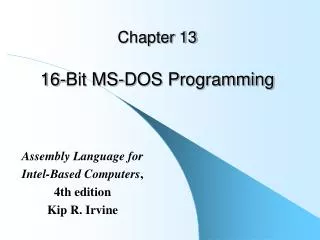
Bit-addressable RAM • The bit-addressable RAM locations are 20H to 2FH. • Only 16 bytes of RAM are bit-addressable. • 16 * 8 bits = 128 bits (in decimal) = 80H bits (in hex) • They are addressed as 00 to 7FH • Note that the bit addresses 80H to F7H belong to SFR. • See Figure 8-3
Byte address 7F Figure 8-3. 128 Bytes of Internal RAM General purpose RAM 30 Bit-addressable locations 2F 2E 2D 2C 2B 2A 29 28 27 26 25 24 23 22 21 20 Bank 3 1F 18 17 Bank 2 10 Bank 1 0F 08 07 Default register bank for R0 - R7 00
Example 8-8 Find out to which byte each of the following bits belongs. Give the address of the RAM byte in hex. (a)SETB 42H;set bit 42H to 1 (d)SETB 28H;set bit 28H to 1 (b)CLR 67H;clear bit 67 (e)CLR 12 ;clear bit 12 (decimal) (c)CLR 0FH;clear bit 0FH (f)SETB 05 Solution: (a) RAM bit address of 42H belongs to D2 of RAM location 28H (b) RAM bit address of 67H belongs to D7 of RAM location 2CH (c) RAM bit address of 0FH belongs to D7 of RAM location 21H (d) RAM bit address of 28H belongs to D0 of RAM location 25H (e) RAM bit address of 12 belongs to D4 of RAM location 21H (f) RAM bit address of 05 belongs to D5 of RAM location 20H
Example 8-9 The states of bits P1.2 and P1.3 of I/O port P1 must be saved before they are changed. Write a program to save the status of P1.2 in bit location 06 and the status of P1.3 in bit location 07. Solution: CLR 06 ;clear bit address 06 CLR 07 ;clear bit address 07 JNB P1.2,OVER ;If P1.2=0,jump SETB 06 ; OVER:JNB P1.3,NEXT ;If P1.3=0,jump SETB 07 ; NEXT:...
Single-bit Operations • Instructions that are used for single-bit operations are given in Table 8-1. • These instructions can be used for any bit. • Some instructions that allow single-bit operations, but only along with the carry flag (CY). • In 8051, there are several instructions by which the CY flag can be manipulated directly. • See Table 8-3.
Example 8-10 Write a program to save the status of bits P1.2 and P1.3 on RAM bit locations 6 and 7, respectively. Solution: CY is used as a bit buffer. MOV C,P1.2 ;save status of P1.2 on CY MOV 06,C ;save in RAM bit location 06 MOV C,P1.3 ;save status of P1.3 on CY MOV 07,C ;save in RAM bit location 07
Example 8-11 (1/2) Assume that RAM bit location 12H holds the status of whether there has been a phone call or not. If it is high, it means there has been a new call since it was checked the last time. Write a program to display “New Message” on an LCD if bit RAM 12H is high. If it is low, the LCD should say “No New Messages”. Solution: Use CY to hold the status. Use JNC to check CY flag. We use “LCALL DISPLAY” to display message (see Chap. 12)
Example 8-11 (2/2) MOV C,12H ;copy bit location 12H to JNC NO ;check to see if is high MOV DPTR,#400H ;address of YES_MG LCALL DISPLAY ;display SJMP EXIT ;get out NO: MOV DPTR,#420H LCALL DISPLAY EXIT: ;data to be displayed on LCD ORG 400H YES_MG: DB “New Messages” ORG 420H NO_MG: DB “No New Messages” MOV C, 12H Jump if CY=0 Test Not Jump if CY ≠0 Display NO_MG Display YES_MG SJMP EXIT EXIT
Example 8-12 Assume that the bit P2.2 is used to control the outdoor light and bit P2.5 to control the light inside a building. Show how to turn on the outside light and turn off the inside one. Solution: STEB C ;CY=1 ORL C,P2.2 ;CY = P2.2 ORed with CY MOV P2.2,C ;turn it “on” CLR C ;CY=0 ANL C,P2.5 ;CY=P2.5 ANDed with CY MOV P2.5,C ;turn it off
Reading Ports • When reading ports, there are two possibilities: • Read the status of the input pin • Read the internal latch of the output pin • Readers must study and understand the material on the internal working of ports that is given in Appendix C2. • See Chapter 4. • Table 8-4 shows instructions to read external pins • Table 8-5 shows instructions to read latches
ANL ANL P1,A ORL ORL P1,A XRL XRL P1,A JBC PX.Y, TARGET JBC P1.1, TARGET CPL CPL P1.2 INC INC P1 DEC DEC P1 DJNZ PX, TARGET DJNZ P1,TARGET MOV PX.Y,C MOV P1.2,C CLR PX.Y CLR P1.3 SETB PX.Y SETB P1.4 Table 8-5: Instructions Reading a Latch (Read-Modify-Write) Mnemonics Example
Read-modify-write Feature • The sequence of actions taken: 1. CPU reads the latch of the port 2. CPU perform the operation 3. Modifying the latch 4. Writing to the pin • Note that 8 pins of P1 work independently. • All read-modify-write instructions use the ports as the destination operand. • That is, these ports are configured as output ports.
You are able to • List the 8051 Assembly language instructions for bit manipulation • Code 8051 instructions for bit manipulation of ports • Explain which 8051 registers are bit-addressable • Describe which portions of the 8051 RAM are bit-addressable • Discuss bit manipulation of the carry flag • Describe the carry flag bit-related instructions of the 8051
Homework • Chapter 8 Problems:7,16,24,25,40,41,44 • Note: • Please write and compile the program of Problems 7,40,41,44.