Design and Simulation of an 8-Bit ALU Utilizing Han-Carlson Carry Network
240 likes | 447 Vues
This project details the design and simulation of an 8-bit Arithmetic Logic Unit (ALU) using a Han-Carlson carry network, achieving a clock frequency of 200 MHz with a power consumption of 25.28 mW. The ALU is capable of performing multiple operations, including addition, subtraction, and logical operations on two 8-bit numbers. The project includes an analysis of gate widths, timing verification, and layout extraction, revealing key insights and lessons learned during the design process while meeting all specifications.

Design and Simulation of an 8-Bit ALU Utilizing Han-Carlson Carry Network
E N D
Presentation Transcript
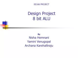
8-Bit ALU Kin Fu Tang Robert Last Joseph Roosma Adnan Alam Advisor: David W. Parent May 8, 2006
Agenda • Abstract • Introduction • Purpose • Simple Theory • Summary of Results • Project (Experimental) Details • Results • Cost Analysis • Conclusions
Abstract • An 8-bit ALU using a Han-Carlson carry network was designed. It was shown through simulations to operate at a clock frequency of 200MHz, using 25.28mW of Power and requiring an area of XxX mm2
Introduction • An ALU is an important building block in digital systems which carries out the basic arithmetic and logic. • Depending on the supplied control signals, the ALU is designed to carry out the following operations on two 8-bit numbers: ADD, SUB, AND, OR, XOR, NAND, NOR, and many others.
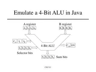
Block Diagram 8-bit Input DFF AOI3333 (G, HS) Control Signals (ADD, OR, etc.) Han-Carlson Carry Network XOR DFF 8-bit Output
Summary of Results • Determination of Gate Widths • Final schematic, and • Simulations: NC Verilog and SPICE • Final layout • Verification of layout and extraction.
Schematic - Overall LONGEST PATH DFF INVERTER P G AOI3333 HAN-CARLSON NETWORK XOR BLACK CELL DFF
Simulation – SPICE – Worst Case (Schematic) τPLH3.76ns
Simulation – SPICE – 2-bit Addition(Schematic) Output Input
Simulation – SPICE – Power Usage(Schematic) P = 25.28mW
Layout - Overall DFF AOI3333 HAN-CARLSON NETWORK XOR DFF
Cost Analysis • Estimated time spent on each phase of the project: • Verifying logic: 8 hours • Verifying timing: 10 hours • Layout: 45 hours • Post extracted timing: 8 hours ___________TOTAL: 71 hours
Lessons Learned • Start early. • Make sure that the overall logic works first (with actual transistors). • Once the overall timing is agreed upon, it’s hard to go back and make changes. • Use cell based design, it’s less confusing. • Save time for troubleshooting.
Summary • An 8-bit ALU which operates at a clock frequency of 200MHz was designed and simulated. • All specifications (clock and power) were met.
Acknowledgements • Dr. David Parent • Cadence Design Systems • Irma Alarcon (Lab Technician)