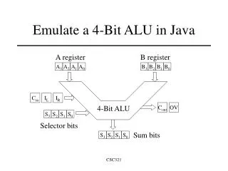
4-BIT ALU
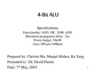
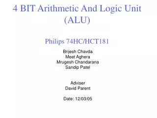
4-BIT ALU. VLSI DESIGN ECE 8460 Spring 2003. Project submitted By RAMANA K VINJAMURI. Introduction. ALU – Arithmetic Logic Unit Addition Subtraction Logical functions COMPARATOR -


4-BIT ALU
E N D
Presentation Transcript
4-BIT ALU VLSI DESIGN ECE 8460 Spring 2003 Project submitted By RAMANA K VINJAMURI
Introduction • ALU – Arithmetic Logic Unit • Addition • Subtraction • Logical functions • COMPARATOR - • Comparing two inputs • A<B (SLT) • A>B (SGT) • A=B (SEQ)
Introduction • How we developed the Circuit ? • Written a code in VHDL. • Obtained a gate level circuit diagram. • Developed minimum gates combinational logic diagram. • Used LASI tool. • Constructed the layout . • Finally on a 2mm chip.
4-Bit ALU Standard Cells used…. We used a total gates of : • INVF 101 • NANF 201 • NANF 301 • NANF 401 • NORF 201 • NORF 301 • NORF 401 • XORF 201 • 61 Inverters • 55 Nand gates • 14 Nor gates • 7 Xor gates Total number of gates to construct our ALU are : 137
Description of functionality Select signals Functionality
Power Dissipation Current magnitude Average current Average current is 1.850mA Voltage is 5v Average power dissipation is 9.25mW
Propagation Delay Propagation delay is found to be 6ns from input to output
Using as a Comparator Given input A as 1111 and B as 0000 and 1111 alternatively as pulses, We can see the SGT is high at B=0000 and low at B=1111 Also when B=1111 SEQ is high.
Using as OR function Given A=0101 and B as 1010 We get the output as 1111
Using as AND Given A=1011 and B as 1010 We get the output as 1010
Using as XOR Given A=1010 and B as 1010 We get the output as 1010
Using as a BUFFER Given A as 1001 and got the output as 1001 Given A as 0001 and got the output as 0001
As a complement for input A Given A as 0011 and got the output as 1100
Using as a Subtractor Subtraction A”1101” and B”0001” we get F=”1100”
MOSIS Submission • Request new project ID : • Request : PROJECT • Account : Alpha • D-Name: RANA • D-Password:service99 • P- Name: CHIP • P- Password: service • Phone: 610-225-3004 • Technology : MOSIS • Size : 1.56mm2 • Pads: 40 • Package : DIP40 • Quantity: 1 • Description: 4BIT ALU • Request : END
MOSIS Submission • Request : SUBMIT • ID:542154 • P-Password :SERVICE • Layout checksum :212565 • Layout Format : GDS • Top Structure : QCELL • Layout : ftp://123.23.456/ravi/rana/qcell • Request: END
Project Summary • Total number of gates : 137 • Total chip size is :1.568mm2 • Average current required is : 1.850mA • Working voltage is : 5v • Power dissipation is : 9.25mW • Delay between input and output is : 6ns • Maximum clock frequency is : 166.66MHz