Download
1 / 23
230 likes | 714 Vues
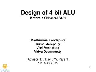
Design of 4-bit ALU Motorola SN54/74LS181. Madhurima Kondepudi Suma Marepally Vani Venkatrao Vidya Devarasetty Advisor: Dr. David W. Parent 11 th May 2005. Agenda. Abstract Introduction Why Simple Theory Back Ground information (Lit Review) Summary of Results

E N D
Design of 4-bit ALUMotorola SN54/74LS181 Madhurima Kondepudi Suma Marepally Vani Venkatrao Vidya Devarasetty Advisor: Dr. David W. Parent 11th May 2005
Agenda • Abstract • Introduction • Why • Simple Theory • Back Ground information (Lit Review) • Summary of Results • Project (Experimental) Details • Results • Cost Analysis • Conclusions
Abstract • Goal is to design a 4-bit ALU driving a load of 30fF in 5ns. • Perform 16 Arithmetic operations. • Perform 16 Logical operations. • The data should be transferred at clock rates of 200 MHz, with .6ns setup and hold times. • Maximum power is 50mW. • Maximum area is 500x500µm2
Introduction Why this project? • The Arithmetic and logic Unit is a building block of several circuits. • Challenging to design a 16 logic level design working at 5ns. • Design consists of different kinds of logic… Ripple Carry Adder, Subtractor, Transfer Data, DFF, Decoders, Inv, Nand, Nor, Xor, etc.
Function Table A, B = 4 Bit Input, M , S0, S1 = Status Control Pin Cn = Carry in
Project Summary • The ALU performs 16 Arithmetic functions and 16 Logical functions at 200MHz. • Uses Ripple carry adder to perform addition. • Design uses maximum power of 18.9mW • Maximum area is 403 x 335µm2
Longest Path Calculations Total Propagation delay for the longest path = 2.86ns
Schematic- Top-Level Schematic - Top Level
Simulation-1(Logical Operations) F = (AB) ' F = A' F = (A'+B) F = Logical 1 S=4, M=1, (A+B)` F = (A+B) ' F = (A XOR B) ' F = B' F = A+B'
Simulation-2 (Arithmetic Operations) F = AB - 1 F = A - 1 F = AB'- 1 F = minus 1 F = A plus (A+B) F = AB plus(A+B') F = A plusB
Verification DRC Results NETLISTS MATCH
Transient Response A=0, B=1, M=0, S=E, F0 = F1=F2 = F3 = 0, F = AB plus A
Transient Response -Power Total Power = 18.9mW
Results • The ALU performs all 32 functions at a 200MHz clock and a load of 30fF. • Power dissipation is 18.9mW. • Area of the layout is 403 x 335µm2
Cost Analysis • Time spent on each phase of the project • Logic check 1 week. • Gate level design 2 weeks. • Integration of schematic blocks and verification 2weeks. • Layout 2 weeks. • Post extraction check 3 days.
Conclusions • Designed and tested almost all the design units that we learnt in the class. • Designed a 4-Bit ALU that performs sixteen arithmetic and sixteen logical functions at 200MHz frequency with setup and hold time 0.6ns, driving up to 30fF. • This circuit can be used as a building block for 16/32-bit ALU. • The Logic design can be modified to perform more functions.
Lessons Learned • Uniform cell height. • No bends in the poly. • Learned to fix LVS errors using extracted view.
Acknowledgements • Thanks to Cadence Design Systems for the VLSI lab • Thanks to Professor David W. Parent for his guidance.