Download
1 / 34
421 likes | 1.43k Vues
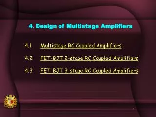
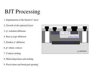
2 . Design of BJT amplifiers. 2.1 Types of BJT amplifiers 2.2 BJT amplifier biasing design 2.3 BJT Optimum Q point 2.4 CE amplifiers and Design 2.5 CE with R E amplifiers and Design 2.6 EF amplifiers and Design 2.7 CB amplifiers and Design

E N D
2. Design of BJT amplifiers 2.1 Types of BJT amplifiers 2.2 BJT amplifier biasing design 2.3 BJT Optimum Q point 2.4 CE amplifiers and Design 2.5 CE with RE amplifiers and Design 2.6 EF amplifiers and Design 2.7 CB amplifiers and Design 2.8 Design of RC Coupled BJT amplifiers
Rac = Rc//RL Rdc = Rc+RE Rac =( Rc//RL)+RE Rdc = Rc+RE (a) Common Emitter High AV and low Ri Voltage amplifications (b) Common Emitter with RE Low AV and high Ri Stability applications Rac =( Rc//RL)+(RE//Ri) Rdc = Rc+RE Rac = RE//RL Rdc = RE (c) Emitter Follower Very low Ro and high Ri Buffer applications (d) Common Base Very low Ri and high AV High Frequency applications 2.1 Types of BJT amplifiers
R2 Design equation R1 Design equation VBB Design equation RB Design condition 2.2 BJT amplifier biasing design Designing the biasing equation
Rac = Rc//RL Rdc = Rc+RE 1. Find VCC point 2. Draw Rdc line from VCC common emitter 3. Locate Q-pt at crossing of IB and Rdc line 4. Draw Rac line passing Q-pt. DV = RacxICQ 5. Note ICQ and VCEQ 2.3 BJT Optimum Q point
IC(pp) VCE(pp)=VO(pp) 6. When sine wave signal is applied to the Base circuit of BJT 6. sine wave will vary IBQ to produce IB(pp) and therefore IC(pp) and VCE(pp) will be produced. Now VCE(pp) will becomes output voltage at the collector.
lower half cycle of the output voltage wave will be clipped due to saturate IC If Q point is at High IC When the Input wave increases IB(pp) , then VCE(pp) will increase
upper half cycle of the output voltage wave will be clipped due to cutoff IC If Q point is at Low IC When the Input wave increases IB(pp) , then VCE(pp) will increase
(c) If the Input wave increases IBQ , then both ICQ and VCEQ will increase where both half cycle of the output voltage wave will be clipped simultaneously due to cutoff and saturation in the case shown because of optimum collector current. Vo(pp) Design equation Optimum ICQ Design equation BJT Optimum Q point Design Equation Design of Optimum Collector current
Summary of Design Equations(dc design equations for all CE, CE with RE, EF, CB configurations) Optimum ICQ Design equation RB Design equation if no other ac specifications are not given VBB Design equation for any RB VBB Design equation if RB = 0.1 b RE R2 Design equation R1 Design equation Vo(pp) Design equation
Rac = Rc//RL Rdc = Rc+RE common emitter Design Example • Draw CE amplifier circuit • Design bias resistance R1 and R2 and find the maximum output voltage swing Vo(pp) Given specifications are VCC= 5V, RC = 1k-W , RL = 1k-W , RE= 100W, b =180
2.4 CE amplifier and Design • Why the circuit below is CE (Common Emitter) amplifier? 1. input to the amplifier is at Base 2. output of the amplifier is at Collector 3. so Emitter becomes common to both input and output and is called CE
1. all capacitors short and replace VCC with ac ground 2. Then replace BJT with it’s equivalent circuit, label all components CE amplifier analysis 3. Calculate Av ,Ri, Ro, Ai, from the equivalent circuit
Circuit Voltage gain Input resistance Output resistance Current gain CE amplifier design equations (in addition to previous chapter upon dc design equations)
CE amplifier design Example 1 Draw the (CE) amplifier circuit Given specifications are: b= 200, VCC = 10V, design with maximum (optimum) output voltage swing, RC= RL= 2kW, RE = 0.4kW, Ri= 0, Rin = 1.5kW Design bias R1 and R2, find voltage gain,and undistorted output voltage swing.
Example 2 • Draw the (CE) amplifier circuit • Given specifications are: b= 200, VCC = 10V, optimum output voltage design, RC= RL= 2kW, RE = 0.4kW, Ri = 0.1kW • Design bias R1 and R2 , so that Av= vo / vi > 100 • Find undistorted output voltage swing.
3. RE is active as there is no CE 2.5 CE with RE amplifier and Design • Why the circuit below is CE with RE amplifier? 1. input to the amplifier is at Base 2. output of the amplifier is at Collector 4. so Emitter becomes common to both input and output with RE activeand is called CE with RE
CE with REamplifier analysis 1. all capacitors short and replace VCC with ac ground 2. Then replace BJT with it’s equivalent circuit, label all components 3. Calculate Av ,Ri, Ro, Ai, from the equivalent circuit
Circuit Voltage gain Output resistance Input resistance Current gain CE with REamplifier design equations (in addition to previous chapter upon dc design equations)
CE with RE amplifier design Example 1 Draw the (CE with RE ) amplifier circuit. Given specifications are: b= 200, VCC = 11.17V,, optimumoutput voltage swing, RC= RL = 2kW, RE = 0.4kW, Ri = 0.1kW. Design bias R1 and R2 , so that Rin = vin / iin = 10 kW find undistorted output voltage swing and voltage gain Av = vo/vin and AvT = vo/vi
2.6EF amplifier and Design 1. input to the amplifier is at Base 2. output of the amplifier is at Emitter 3.Collector becomes common to both input and output and the amplifier is Common Collector (CC) amplifier or Emitter Follower (EF) amplifier
EF amplifier analysis 1. First replace VCC with ac ground and all capacitors short.2. Then replace BJT with it’s equivalent circuit, label all components. 3. Calculate Av ,Ri, Ro, Ai, from the equivalent circuit
To find Roall voltage sources are shorted and with it’s equivalent circuit, calculate Ro, Ai
Circuit Voltage gain Input resistance Output resistance Current gain EF amplifier design equations (in addition to previous chapter upon dc design equations)
EF amplifier design Example 1 Draw and design EF amplifier with following specifications: Specified RL= 100W, b= 60, VCC = 12V Design RE , R1 , R2 , so that Rin = 1kW.Find Ro if Ri=100Wand Vo (pp)
Example 2 Draw and design EF amplifier with following specifications: Specified b= 60, Rin= 10kW, IC = 10mA. Design VCC , RE = RL, R1 , R2 , so that Ai= 10, and find Ro if Ri=100W and Vo (pp)
3.2 CB amplifier and Design 3.2.1 CB amplifier without CB 2. output of the amplifier is at Collector 1. input to the amplifier is at Emitter 3. Base becomes common to both input and output and the amplifier is Common Base (CB) amplifier
3.2.1 CB amplifier analysis (without CB) First replace VCC with ac ground and all capacitors short.Then replace BJT with it’s equivalent circuit, label all components. Calculate Av ,Ri, Ro, Ai, from the equivalent circuit
RB= 0 RB= 0 3.2.2 CB amplifier analysis (with CB)
3.2.1 CB amplifier without CB 3.2.2 CB amplifier with CB CB amplifier design equations (in addition to previous chapter upon dc design equations) Voltage gain Input resistance Output resistance Current gain Circuits
CB amplifier design Example 1 Draw and design CB amplifier without CB with following specifications: RL = 2k W, b= 100, RE = 400W, VCC = 24V Design R1 , R2 , so that Av= 20and find Ai , Rin and Vo (pp)
Example 2 Draw and design CB amplifier with CB for following specifications: RL= 2kW, b= 100, RE= 400W, VCC = 24V Design R1 , R2 , so that Av=200 and find Ai , Rin and Vo (pp)
IL Iin Ro Ri2 Ri AV1 AV2 AVT 2.8 Design of RC Coupled BJT amplifiers Cascade amplifier consists of two or more amplifiers using individual power supply VCC for each stage. The load on the first amplifier is the input of the second amplifier and so on. For each Cascaded amplifiers, dc design is the same as before Ri2 For both Cascaded amplifiers, ac design is from the followings:
IL Iin Design Example Draw and design a two-stage CE-CE cascade amplifier for the following specifications: VCC = 12V, b = 200 (both), RE1= RE2= 50W, RC1= RC2 = RL =600W,, Ri2= 300W, Ai=5,000 Design the biasing resistances of the stages, R!!,R21,R12,R22 # What is the Vo(pp) of each stage? # What is the overall voltage gain from the first stage input Vin1 to the output of the second stage Vo2 ? # What is the input resistance Rin1 of the first stage ? # What is the maximum possible input Vin1 at the first stage? Second CE stage design