Download
1 / 80
810 likes | 1.02k Vues
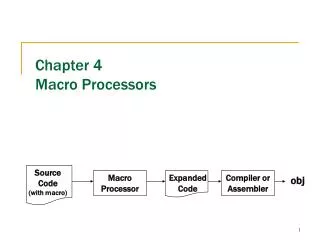
How to Build Macro-Models in Tina SPICE Part 1: Text Macro-Model Creation Text SubCircuit Creation Symbol Creation Macro-Model Creation Part 2: Schematic Macro-Model Creation Schematic SubCircuit Creation Symbol Creation Macro-Model Creation Tim Green May 4, 2006.

E N D
How to Build Macro-Models in Tina SPICE Part 1: Text Macro-Model Creation Text SubCircuit Creation Symbol Creation Macro-Model Creation Part 2: Schematic Macro-Model Creation Schematic SubCircuit Creation Symbol Creation Macro-Model Creation Tim Green May 4, 2006
Part 1: Text Macro-Model Creation Text SubCircuit Creation Symbol Creation Macro-Model Creation
Part 1: Text Macro-Model Creation Text SubCircuit Creation Equivalent Schematic of Text SubCircuit Circled numbers are Node numbers * Indicates Comment * TG Simple 159Hz LPF *Connections..... VIN VOUT GND .SUBCKT LPF 1 2 3 R1 1 2 1k C1 2 3 1u .ENDS LPF .SUBCKT statement w/subcircuit name (LPF) All external Nodes to connect subcircuit (1,2,3) Component types/names and Node connections End subcircuit statement w/subcircuit name (.ENDS LPF)
Part 1: Text Macro-Model Creation Netlist Creation Open “Netlist Editor” in Tina Schematic Editor
Part 1: Text Macro-Model Creation Netlist Creation Enter Text SubCircuit into “Netlist Editor”
Part 1: Text Macro-Model Creation Text SubCircuit Creation “Save File As” either “.cir” or “.mod” in any file folder convenient
Part 1: Text Macro-Model Creation Text SubCircuit Creation Close “Netlist Editor”
Part 1: Text Macro-Model Creation Symbol Creation Open “Schematic Symbol Editor”
Part 1: Text Macro-Model Creation Symbol Creation “File”, “Open”, “Devices.DDB” This is the Device Database file which hold all schematic symbols for Tina.
Part 1: Text Macro-Model Creation Symbol Creation - Modify Select a device form the list at the right and then select “Edit Device”, If you want to use an existing symbol and modify it
Part 1: Text Macro-Model Creation Symbol Creation - Modify After existing symbol edits are completed, select “Edit”, “Pin Order…”
Part 1: Text Macro-Model Creation Symbol Creation - Modify 1 2 3 Hidden Pin Numbers * TG Simple 159Hz LPF *Connections..... VIN VOUT GND .SUBCKT LPF 1 2 3 R1 1 2 1k C1 2 3 1u .ENDS LPF Ensure “Pin Order” matches the order in the Text SubCircuit. If not re-arrange the pin order using the up and down arrows until the pin order is correct.
Part 1: Text Macro-Model Creation Symbol Creation - Modify After existing symbol edits are completed, select “Device Properties”
Part 1: Text Macro-Model Creation Symbol Creation - Modify Give the edited symbol a new, unique name and click “OK”
Part 1: Text Macro-Model Creation Symbol Creation - Modify “Add Device”, Add the new symbol to the list at the right. Use + button or drop down menu.
Part 1: Text Macro-Model Creation Symbol Creation - Modify Save the updated Device Database as “DEVICES.DDB” Warning: Backup the original “DEVICES.DDB” File in case there is a problem.
Part 1: Text Macro-Model Creation Symbol Creation - New “Device”, “New Device”, If you want to create your own unique symbol for the Macro-Model
Part 1: Text Macro-Model Creation Symbol Creation - New Create desired outline for symbol. Keep grey “crosshair arrows” and “+ circle” geometrically centered inside of symbol outline. “Label” will be where “Ref Designator” appears as default on schematic when symbol is placed.
Part 1: Text Macro-Model Creation Symbol Creation - New “Drop down menu allows for pin rotation during pin placement Place pins by drag and drop where desired. Red x is electrical connection point. Grey box can move pin number anywhere desired.
Part 1: Text Macro-Model Creation Symbol Creation - New Double click on each pin to select the “Pin Properties”. If you want a name on your pin unselect “Show”. For your Symbol to be available to build your Macro-Model form the Text SubCircuit it must be built with the EXACT same number of pins and use the same pin numbers on the pins as your Text SubCircuit
Part 1: Text Macro-Model Creation Symbol Creation - New Enter desired pin name here Click on “T” to create a text label for your symbol pin. A crosshair will appear in the window. Click the mouse once and a Text Entry Box will pop up. After text entry click “OK” and name will appear. Move pin name where desired.
Part 1: Text Macro-Model Creation Symbol Creation - New After existing symbol edits are completed, select “Edit”, “Pin Order…”
Part 1: Text Macro-Model Creation Symbol Creation - New 1 2 3 Hidden Pin Numbers * TG Simple 159Hz LPF *Connections..... VIN VOUT GND .SUBCKT LPF 1 2 3 R1 1 2 1k C1 2 3 1u .ENDS LPF Ensure “Pin Order” matches the order in the Text SubCircuit. If not re-arrange the pin order using the up and down arrows until the pin order is correct.
Part 1: Text Macro-Model Creation Symbol Creation - New After existing symbol edits are completed, select “Device Properties”
Part 1: Text Macro-Model Creation Symbol Creation - New Give the edited symbol a new, unique name and click “OK”
Part 1: Text Macro-Model Creation Symbol Creation - New “Add Device”, Add the new symbol to the list at the right. Use + button or drop down menu.
Part 1: Text Macro-Model Creation Symbol Creation - New Save the updated Device Database as “DEVICES.DDB” Warning: Backup the original “DEVICES.DDB” File in case there is a problem.
Part 1: Text Macro-Model Creation Macro-Model Creation Either “Exit” or minimize the “Schematic Symbol Editor”
Part 1: Text Macro-Model Creation Macro-Model Creation Select “Re-read symbol database”
Part 1: Text Macro-Model Creation Macro-Model Creation Start the Tina “New Macro Wizard”
Part 1: Text Macro-Model Creation Macro-Model Creation Enter “Name” for the new Macro-Model. Click on “Content” and select the desired Text SubCircuit File. Then click “Open”
Part 1: Text Macro-Model Creation Macro-Model Creation Click on “Shape”. The ONLY symbol choices that will appear at the right are ones that contain pin numbers and quantities that EXACTLY match the Text SubCircuit. (i.e., 3 pins and pins numbered 1, 2, 3 corresponding to the Nodes in the Text Subcircuit of 1, 2, 3) Unselect all boxes since we want to use our own symbol for the Macro-Model.
Part 1: Text Macro-Model Creation Macro-Model Creation Highlight desired “Shape” at the right and click “OK” to enter it into the “Shape” dialog box.
Part 1: Text Macro-Model Creation Macro-Model Creation If you want a label to appear next to the Ref Designator when you place the Macro-Model on a schematic enter it here under “Label”
Part 1: Text Macro-Model Creation Macro-Model Creation Finish Macro-Model creation and Save the results. Click “OK” and popup window on right will appear. Tina uses “.TSM” as Macro Schematics file extension. After creating or using default File name and choosing the folder to store the Macro-Model in click “Save”
Part 1: Text Macro-Model Creation Macro-Model Use Select “Re-read symbol database”
Part 1: Text Macro-Model Creation Macro-Model Use In the Tina “Schematic Editor” choose “Insert”, “Macro”. From the desired folder select the Macro for insertion into the Schematic Editor and click “Open”
Part 1: Text Macro-Model Creation Macro-Model Use Now the Macro-Model may be connected and used in the Schematic Editor as a normal Macro-Model.
Part 2: Schematic Macro-Model Creation Schematic SubCircuit Creation Symbol Creation Macro-Model Creation
Part 2: Schematic Macro-Model Creation Schematic SubCircuit Creation Create a schematic for the SubCircuit in the “Schematic Editor”. Add “Macro pin” connections for the desired Macro-Model pins.
Part 2: Schematic Macro-Model Creation Schematic SubCircuit Creation Double click on each “Macro pin” and type a desired pin number in the “Label” box. When completed click on “OK”.
Part 2: Schematic Macro-Model Creation Schematic SubCircuit Creation When Schematic SubCircuit is complete use “File”, “Save As” in desired folder as a Tina schematic “.TSC”
Part 2: Schematic Macro-Model Creation Symbol Creation Open “Schematic Symbol Editor”
Part 2: Schematic Macro-Model Creation Symbol Creation “File”, “Open”, “Devices.DDB” This is the Device Database file which hold all schematic symbols for Tina.
Part 2: Schematic Macro-Model Creation Symbol Creation - Modify Select a device form the list at the right and then select “Edit Device”, If you want to use an existing symbol and modify it
Part 2: SchematicMacro-Model Creation Symbol Creation - Modify After existing symbol edits are completed, select “Device Properties”
Part 2: SchematicMacro-Model Creation Symbol Creation - Modify Give the edited symbol a new, unique name and click “OK”
Part 2: SchematicMacro-Model Creation Symbol Creation - Modify “Add Device”, Add the new symbol to the list at the right. Use + button or drop down menu.
Part 2: SchematicMacro-Model Creation Symbol Creation - Modify Save the updated Device Database as “DEVICES.DDB” Warning: Backup the original “DEVICES.DDB” File in case there is a problem.
Part 2: SchematicMacro-Model Creation Symbol Creation - New “Device”, “New Device”, If you want to create your own unique symbol for the Macro-Model