Status Update on the VUV-FEL and TESLA Test Facility Developments (March 2005)
This document provides a detailed status update on the VUV-FEL and the TESLA Test Facility (TTF) as of March 7, 2005. It outlines the completion of installation for key components such as RF guns, accelerator modules, and bunch compressors, along with ongoing commissioning activities. Significant achievements include the first lasing established on January 14, 2005, detailed measurements of beam emittance, and photon pulse energy enhancements. Future considerations for further enhancements and challenges related to beam stability and diagnostics are also discussed.

Status Update on the VUV-FEL and TESLA Test Facility Developments (March 2005)
E N D
Presentation Transcript
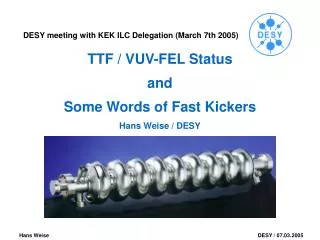
TTF / VUV-FEL StatusandSome Words of Fast KickersHans Weise / DESY DESY meeting with KEK ILC Delegation (March 7th 2005)
RF gun accelerator modules collimator undulators bunch compressor bunch compressor FEL experimental area bypass Laser 4 MeV 150 MeV 450 MeV 1000 MeV TESLA Test Facility Linac – Phase II FEL User Facility in the nm Wavelength Range (VUV) and R&D for the ILC
TTF / VUV-FEL Status as of January 13th, 2005 • The VUV-FEL Set-up: • installation completed until end of 2004 • includes RF gun • five accelerator modules • two bunch compressors • electron beam collimation • electron and photon beam diagnostics • undulator section • still missing are • the 3.9 GHz rf system at the end of the first accelerator module • (needed for short wavelength FEL operation, scheduled for 2006) • some electron beam diagnostics, esp. beam position monitors • sixth accelerator module to increase the electron beam energy to 1 GeV • the photon beam transport to the user‘s experimental hall • the user‘s photon beam lines (to be commissioned until 5/2005)
Electron beam commissioning done with single bunches per bunch train Measured beam emittance (90%) at 120 MeV (BC2 section) is 1.3 pi mm mrad in both planes without compression at 0.5 nC; compression slightly decreases beam quality (as expected) but the beam quality seems to be good enough for lasing at 30 nm; shorter wavelengths need 3.9 GHz system in order to keep the emittance small. Chosen beam energy is 450 MeV, thus corresponding to 30 nm First spontaneous spectrum was taken in 12/2004 At present beam based alignment is used to find the correct electron beam orbit inside the undulator, i.e. first lasing should happen soon. VUV-FEL Status as of January 13th, 2005
First lasing established on January 14th!!! average bunch charge 0.6 nC first accel.module ACC1 approx 6 deg off-crest electron beam energy at BC2 set for 125 MeV accel.modules ACC2/3 on-crest (within 1-2 degrees) accel. BC3 (bunch compressor) on with currents set for 380 MeV beam energy in undulator 450 MeV undulator optic: FOFO and all undulator correctors off, quadrupole movers have not been activated. FEL gain: 1E5 (saturation would correspond to 1E7) Photon pulse energy ~1 micro-Joule Photons per pulse 5E11 photons/sec*mm2*mrad2*0.1BW VUV-FEL Status as of January 14th, 2005 • We now have six weeks of SASE operation • Photon pulse energy increased to typ. 5 µJ • (a factor 2 below saturation) • Photon beam parameters measured with • excellent agreement to theoretical predictions • Stable FEL operation over typ. 15 minutes; then • slight tuning necessary • 90% emittance of compressed bunches approx. • 1.6 mm mrad in both planes • some control loops established in order to • stabilize SASE • still some trouble with the beam orbit inside • the undulator • At present some shut-down activities • connect undulator beamline with user‘s photon • beam lines • modify interlock system • Restart on March 21st.
RF gun accelerator modules collimator undulators bunch compressor bunch compressor FEL experimental area bypass Laser 4 MeV 150 MeV 450 MeV 1000 MeV VUV-FEL Setup / Overall Layout accelerator modules undulator section
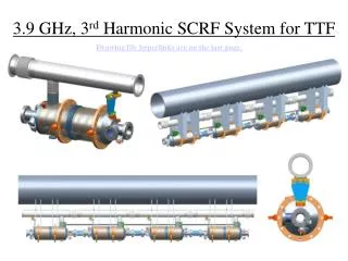
TTF / VUV-FEL as Prototype for the XFEL Injector σz = 2.0 mm 112 µm 22 µm RF Gun s.c. Acc. 3rd harm. Structure s.c. Booster Linac Bunch Compressor Main Linac 100 MeV 500 MeV The goals for the XFEL: charge 1nC x,y 1.4 µm z ~ 20 µm (80 fs) E, uncorr < 2.5 MeV At TTF and PITZ (DESY) we are already close to these parameters.
TTF2 / VUV-FEL Tunnel Layout The TTF2 Tunnel installation basically follows the old TESLA design… With all its advantages and disadvantages.
accelerator module klystron RF pulse cable XFEL Linac Tunnel Layout Accelerator is housed in a 5.2 m diameter tunnel ~ 15 - 30 m underground. Klystrons in tunnel are connected to modulators in an external hall by 10kV pulse cables. Preferred installation concept is suspension from tunnel ceiling
RF Unit of the XFEL (32 cavities) var. Q_ext with adjustable coupler and/or waveguide tuner 5 MW RF source De-rated 10MW MBK Bouncer-type modulator Acc 1 Acc 2 Acc 3 Acc 4 eight 9-cell Nb cavities at 2K, Q0=1010 12m TTF-like acc. modules
circulator stub tuner (phase & Qext) coaxial coupler DAC DAC ADC ADC RF Operation of s.c. Cavities TTF RF Unit 1 klystron for 2 accelerating modules 8 nine-cell cavities each vector modulator MBK Klystron Mechanical tuner (frequency adj.) Low Level RF System cavity #1 cavity #8 pickup signal vector sum accelerator module 1 of 2 vector demodulator
Cavity quench detection algorithms and exeption handling procedures analyze the probe signals... Stable Module #1* operation with slowly but steadily increased gradient 1st quench: Cavity 2 Eacc=19 MV/m 2nd quench: Cavity 6 Eacc=21 MV/m 3rd quench: Cavity 1 Eacc=24 MV/m RF Operation of Accelerator Modules Above its Performance Limit (e.g. Module 1*)
RF Operation of Accelerator Modules Above its Performance Limit (e.g. Module 1*) • The maximum operating gradient of s.c. cavities • is set by cavity quench, field emission, or • Q-degradation – not by structure breakdown • is not a hard limit. A too high gradient results in increased • cryogenic load, radiation, and dark current • does not trip off cavities in ns but in typ. 100 µs • if cavities are operated at the threshold • An exception handler as part of the LLRF can avoid quenches. • Action can be taken prior to the next pulse. • Consequences for the machine safety are very positive, • i.e. correctly injected bunches will not be lost in the linac. In a high gradient long pulse run in spring 2002, an accelerator module was operated with stable beam (5 mA, 800 µs) close to its gradient limit. The acc. module was operated with a typ. module on-time of 90% at increasing gradients: 39 days at 19.5 MV/m, 800 µs, 5 Hz 4 days at 20.0 MV/m, 800 µs, 1 Hz 1 Hz operation due to beam oper. 6 days at 21.5 MV/m, 800 µs, 1 Hz laser + gun were limited
TTF Cavities above 25 MV/m Gradient Cav.5 @ ACC1 was electropolished and reaches 35 MV/m flat top after module installation 10 out of 16 cavities in modules ACC4 / ACC5 can be operated flat top at approx. 29 MV/m
Dark Current vs. RF phase with respect to neighbouring cavities is just as expected (max min) over pi/2 Dark Current Measurement • The on-axis dark current was measured for modules ACC4 / ACC5. • Only one cavity in module ACC5 produced a mentionable dark current. • captured dark current could be • measured at the exit of ACC5 • there was no d.c. from this cavity • at the entrance of ACC4 • the d.c. decreased as a function of time • after module commissioning (August 2003) • 100 nA at 16 MV/m increasing by a • factor 10 for each 4.4 MV/m gradient step • i.e. approx. 10 µA at 25 MV/m • May 4th • 100 nA at 20 MV/m increasing by a • factor 10 for each 3.7 MV/m gradient step, • i.e. 1.2 µA at 25 MV/m • September 22nd • after a few weeks on-time at 20 – 25 MV/m • 250 nA at 25 MV/m • detuning of cavity no. 6 left over an integrated dark current • of the order of 20 to 25 nA at 25 MV/m average gradient Reminder: The TESLA limit is defined by additional cryogenic losses: The captured d.c. has to stay below 50 nA per cavity. (see TESLA Report 2003-10).
re-commissioning of gun + injector • setup cavity phases ACC2-5 beam energy • setup bunch compression • setup beam linear optics, optimize orbit • commissioning of diagnostics 1st beam (bypass) after adjustment First measurement before adjustment • re-commissioning of gun + injector • setup cavity phases ACC2-5 beam energy • setup bunch compression • setup beam linear optics, optimize orbit • commissioning of diagnostics done done done on-going on-going TTF2 / VUV-FEL Beam Commissioning
setup collimation • emittance measurements and optics matching • beam-based alignment in undulator section • commiss. of photon diag. with spon. emission FEL 30 nm 1 bunch MCP Diagn. Beam A. Fateev et al., Dubna TTF2 / VUV-FEL Beam Commissioning Ion pump wirescanner quadrupole stretched wire position control system granite baseplate beam
commissioning of FEL diagnostics • study of FEL beam, compression schemes, etc. • establish reproducible settings, etc. Saturation & 6-100 nm photon diagnostics gas absorber photon diagnostics beam dump LINAC tunnel FEL hall PETRA tunnel TTF2 / VUV-FEL Beam Commissioning
1011 Electro-polished Cavities Measured in Vertical Test Unloaded Quality Factor 1010 Accelerator Module ACC6 with electro-polished cavities should first be tested in a separate test stand. Schedule: a.s.a.p., but not before end of 2005. 109 Accelerating Gradient (MV/m) 0 10 20 30 40 TTF2 / VUV-FEL Outlook Long time operation of all 5 acc. Modules. VUV-FEL Commissioning. First lasing achieved. Stable operation / saturation spring 2005. Start user operation in spring 2005
VUV-FEL Program for 2005 The 2005 operation time is divided in different blocks. Under the assumption of no unexpected shut downs, all requests can be full-filled. Some reserve is within the individual operation periods.
A Fast Pulser for a Fast ATF Kicker The actually used pulser ready for the connection to a fast kicker or the ATF kicker Frank Obier & (Hans Weise)
Stripline used for pulser tests • Test kicker (stripline in vacuum); matching not optimized • 1.5 m cable RG213 between pulser and kicker • reflection at both stripline ends (right plot) • and some ringing as a consequence of the reflection (left plot) Frank Obier & (Hans Weise)
10 ns switch 6.5 kV 70 A All pictures show the same signal but have different scaling in order to look at ripple and ringing. The 10 ns Switch Schalter HTS 80-12UF ton=10ns Frank Obier & (Hans Weise)
Ringing at the end of the pulse. Same pulse, different scaling (zoom) Picture shows ringing at almost acceptable amplitude. Schalter HTS 80-12UF ton=10ns 3,7 % 6,8‰ 40ns Frank Obier & (Hans Weise)
And now a ceramic kicker… Schalter HTS 80-12UF ton=10ns Frank Obier & (Hans Weise)