Mirrors & Lenses
Mirrors & Lenses. Chapter 23. Chapter 23 Learning Goals. Understand image formation by plane or spherical mirrors Understand image formation by converging or diverging lenses. Understand Image Formation by Plane or Spherical Mirrors.

Mirrors & Lenses
E N D
Presentation Transcript
Mirrors & Lenses Chapter 23
Chapter 23 Learning Goals • Understand image formation by plane or spherical mirrors • Understand image formation by converging or diverging lenses
Understand Image Formation by Plane or Spherical Mirrors • Relate the focal point of a spherical mirror to its center of curvature • Locate the image of a real object and determine if the image is: • Real or virtual • Upright or inverted • Enlarged or Reduced
Flat Mirrors • Use a picture to define the following • image and object ( I & O) • image & object distance ( q & p ) • image & object height ( h’ & h ) • real image • virtual image
Summary of Flat Mirrors • The image is as far behind the mirror as the object is in front of the mirror • The image is unmagnified, virtual, & upright
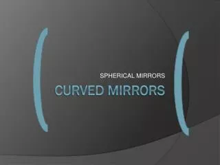
Spherical Mirrors • Two types of spherical mirrors • Concave Mirror • Convex Mirror
Spherical Mirrors • Use a picture to define the following for a concave mirror and convex mirror • principal axis • center of curvature ( C ) • radius of curvature ( R ) • image point and object ( I & O) • image & object distance ( q & p ) • image & object height ( h’ & h )
Spherical Mirrors • When the object is very far from the mirror • The image point is halfway between the center of curvature and the center of the mirror • The image point will be called the focal point • The image distance will be called the focal length
Spherical Mirrors • Magnification Equation M = image height = h’ = - q object height h p
Spherical Mirrors • Mirror Equation 1 + 1 = 2 pq R • Mirror Equation in terms of focal length 1 + 1 = 1 pqf
Front, or real, side R is positive p & q positive incident light ------------- reflected light Back, or virtual, side p & q negative R is negative No light Ray Diagrams (Mirrors)
Ray Diagrams • Steps for Drawing ray diagrams • Ray 1 is parallel to the principal axis & is reflected through the focal point, F • Ray 2 is drawn through the focal point, & reflected parallel to the principal axis. • Ray 3 is drawn through the center of curvature, C, and is reflected back on itself.
Ray Diagrams • The intersection of any two of these rays at a point locates the image
Spherical Abberation • Rays are generally assumed to make small angles with the mirror • When the rays make large angles, they may converge to points other than the image point • This results in a blurred image
Understand image formation by converging or diverging lenses • Know what factors affect the focal length of lenses • Determine by ray tracing: • Location of the image of a real object: • Upright or inverted image • Real or virtual image • Use the thin lens equation to solve problems • Analyze simple situations in which the image formed by one lens is the object for another lens
Thin Lens Shapes • These are examples of converging lenses • They have positive focal lengths • They are thickest in the middle
More Thin Lens Shapes • These are examples of diverging lenses • They have negative focal lengths • They are thickest at the edges
Thin Lenses • Converging Lenses • biconvex • convex-concave • plano-convex
Thin Lenses • Diverging Lenses • biconcave • convex-concave • plano-convex
Front side p positive q negative -------------- incident light Back side p negative q positive ------------- refracted light Ray Diagrams (Lenses)
Sign Convention for Lenses • f is (+) for a converging lens • f is (-) for a diverging lens • R1 & R2 are (+) if the center of curvature is in back of the lens (converging) • R1 & R2 are (-) if the center of curvature is in front of the lens (diverging)
Ray Diagrams (Lenses) • Steps for Drawing ray diagrams • Ray 1 is parallel to the principal axis & is refracted through one of the focal points • Ray 2 is drawn through the center of the lens and continues straight through. • Ray 3 is drawn through the other focal point, & emerges from the lens parallel to the principal axis
Thin Lenses • Thin Lens Equation 1 + 1 = 2 pq R • Thin Lens Equation in terms of focal length 1 + 1 = 1 pqf
Thin Lenses • Magnification Equation M = image height = h’ = - q object height h p
Ray Diagrams for Lenses • Converging Lenses • Object behind the focal point • Object in front of the focal point • Diverging Lenses • Object behind the focal point • Object in front of focal point
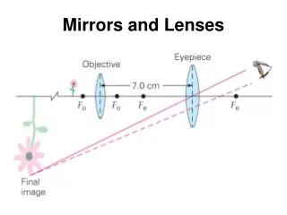
Combination of Thin Lenses • The image formed by the first lens is treated as the object for the second lens
Chapter 23 Resources • http://www.physicsclassroom.com/Class/refrn/U14L5eb.html


![L 33 Light and Optics [3]](https://cdn1.slideserve.com/3393672/l-33-light-and-optics-3-dt.jpg)