
Impact Jet
E N D
Presentation Transcript
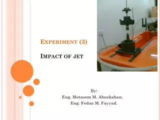
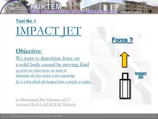
Force ? Test No.1IMPACT JET Objective:We want to determine force on a solid body caused by moving fluid eg; when we shoot water we want to determine the force when it hit something.Jet is when fluids discharged from a nozzle or orifice.by Muhammad Bin Sulaiman x2275 Lecturer FKASA, KUKTEM, Malaysia Impact Jet 1
Testing Approach The formula for a force by moving fluid is given F = .Q.V.(1-cos ) So, how we going to do the testing? We are using balancing concept between two force If we shoot water to a plate upward, the plate will be moving upward. We balance it downward by placing weight on the plate. So force downward exerted by the weight is equal to force upward by the moving fluid. Force downward = Force upward Force downward = mass x gravity And Force upward = .Q.V.(1-cos ) F1 : Force down plate F2 : Force up 2
Testing Approach • Shoot water to plate, the plate up. • Balance it by put weight on the plate. This will bring the plate down. • Adjust the flowrate of the shoot water so that the plate is position at equal position • Force down F1 (by weight) = m x g • Force up F2 (by shoot water based on momentum equation) .Q.V.(1-cos )= (Q / A)2 / 4 = V2 D2/ 4 • Force up and down are balanced and it should be equal. F1 = F2 Experiment value Theoritical value 3
Testing Equipment mass plate water A plexiglass box contains the opening of a brass tube. Above the tube, there is a plate which is free to move vertically and which can be loaded with weights. By regulating the flow in the tube it is possible to obtain a balance between forces of the water jet and the weight. Adjust flow 4
Test No.2DEAD WEIGHT PRESSURE Objective:To perform calibration of a pressure gaugeby comparing experimental and theoretical value. It means that we want to check the pressure in a pressure gauge (Pressure gauge is to measure pressure) if it is correct as just like a penimbang where we put weight to verify it. by Muhammad Bin Sulaiman x2275 Lecturer FKASA, KUKTEM, Malaysia Pressure ? 7
Testing Equipment mass Force = m x g P1 = F/A P2 - Pressure reading Area Pressure Cylinder & Piston connected to pressure gauge. P1 = P2 8
Testing Approach • Connect cylinder &piston to pressure gauge. • Put weight on the piston. • Pressure (P1) exerted on by the weight and area in the piston is: Pressure = Force / Areawhere: Force = mass x gravity • Pressure from experimental (P2) can be taken from pressure gauge. • Both value should be the same. P1 = P2. Theoritical value Experiment value 9
Data sheet Data: Cross-sectional area = m2 Weight of piston = kg Diameter of Piston = m Notes: 1 kg = 9.81 N, True Pressure = M piston + M load 10
Thank you .. 11
Test No.1PUMP IN SERIES & PARALLELObjective:We want to determine pump characteristic curve& pump efficiency for:-- single pump- pump in series - pump in parallel. by Muhammad Bin Sulaiman x2275 Lecturer FKASA, KUKTEM, Malaysia 12
INTRODUCTION Pressure (▲P ) Flowrate (Q) Pump Characteristic Curve It is flowrate versus pressure difference of a pump. Different pump has different pump characteristic curve. This is supply by suppliers. It is like a formula. If we know flowrate thru the pump, then we know pressure difference. Vice versa. 13
Head 1 = 5 ft Location 1 Head 2 = 20 ft Location 2 WHY NEED PUMP The function is: To supply pressure so that water can be moved to location that has a higher head (usually mean higher location) So how to select the pump? First, calculate requirement which is static head (elevation difference divide by 2g) plus head loss between location 1 & 2. If the static head is 15ft (assume=1) and head loss is 5 ft, then the pump must supply head 20 ft. so that water can reach to top. Second, refer to solution which is a pump characteristic curve. If the pressure difference (divide by ) which is 20 ft can be located on the curve, then the pump can supply the flow. However, also look at the flow if it meet your requirement. If it does, then select the pump. ** Refer to Energy equation for detail explanation. 14
ENERGY EQUATION *Energy Equation: P1 + z1 + V12 = P2 + z2 +V22 + HL1-2 2g 2g P1 – P2 = z2 - z1 + HL1-2 where V1=V2 2g So, head pressure difference between 1 & 2 is equal to static head (elevation difference divide by 2g) plus head loss between location 1 & 2. The function of the pump is to supply the head pressure difference (divide by ). 15
Testing Approach In the lab, we want to create this pump characteristic curve and pump efficiency. Pump characteristic is flow versus pressure rise. Pump characteristic curve • To get the flow, we can measure volume & time. • To get the pressure rise, we have to use manometer at inlet and outlet of the pump. • To get the curve varies the flowrate, we control opening of the valve. The efficiency is based on formula: = Q . ▲P / ▲ w 16
Testing Approach P1 P2 Volume time Q = Pump 1 Test 1: Determine pump characteristic curve for single pump 17
Testing Approach Q1 Pump 1 Q Q2 Pump 2 Test 2: for Pump in parallel Q1 Q2 Q Pump 2 Pump 2 Test 3: for Pump in series 18
Testing Approach Pump in series Flowrate across each pump is the same. The overall pressure rise is the sum of the two pumps. If the pumps are identical, then pressure rise is twice of a single pump. h1 h h2 Head (▲P ) Q Flowrate (Q) 19
Testing Approach Pump in parallel Pressure rise across each pump is the same. The overall flowrate is the sum of the two pumps. If the pumps are identical, then flowrate is twice of a single pump. Head (▲P ) Q1 Q2 Q Flowrate (Q) 20
Data sheet Table 1: For a single pump (speed 1400rpm) 21
Thank you .. 22