G E A R S
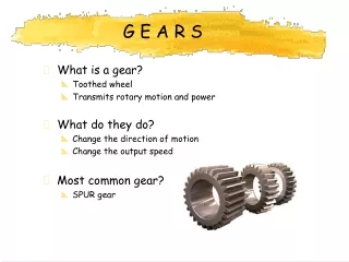
G E A R S. What is a gear? Toothed wheel Transmits rotary motion and power What do they do? Change the direction of motion Change the output speed Most common gear? SPUR gear. SIMPLE GEAR TRAINS. What is a simple gear train? Meshed (interlocking gears) Two or more gears in series


G E A R S
E N D
Presentation Transcript
G E A R S • What is a gear? • Toothed wheel • Transmits rotary motion and power • What do they do? • Change the direction of motion • Change the output speed • Most common gear? • SPUR gear
SIMPLE GEAR TRAINS • What is a simple gear train? • Meshed (interlocking gears) • Two or more gears in series • Input gear = DRIVER • Output gear = DRIVEN • What effect does this have on the output (DRIVEN) • Reverses motion • Changes speed/ power
Movement- multiplier Ratios (Gear Ratio) • What is this? • Ratio of the movement between the gears • Divide number of teeth on DRIVEN by the number on the DRIVER • Practice! • A simple gear train is shown. The driver gear A has 20 teeth, while gear B has 40 teeth. • What is the movement multiplier ratio of the system? • If shaft A rotates anti-clockwise, in which direction does shaft B rotate?
Solutions • Driver = 20 teeth Driven = 40 teeth M.R. = Driven / Driver = 40/20 = 2 • Gear movement ratio is 2 : 1 • A rotates anti- clockwise B rotates clockwise
Speed Ratio • What is this? • Ratio of the speed between the input and output gears • Divide number of teeth on DRIVER by the number on the DRIVEN • Practice! • A simple gear train is shown. The driver gear A has 20 teeth, while gear B has 40 teeth. • Calculate the Speed Ratio
Solutions • Driver = 20 teeth Driven = 40 teeth S.R. = Driver / Driven = 20/40 = 1/2 • Gear speed ratio is 1 : 2
Calculating Output Speed We know from previous work that the SR for the gear train shown is: Driver = 20 teeth Driven = 40 teeth S.R. = Driver / Driven = 20/40 = 1/2 If the driver has a speed of 200rpm, what is the driven speed? Output speed = SR x input speed = ½ x 200 = 100rpm
Idler Gears • What is an IDLER gear? • A third gear inserted between Driver and Driven • Allows Driver and Driven to rotate in same direction • No effect on Speed or Gear Ratio of the system • Usually a small gear (takes up less space)
More Gears!! • Calculate the multiplier ratio for the simple gear train below and then find the speed ratio. If gear A rotates at 250 rpm in a clockwise direction, calculate the output speed. Show all your working. A = 20 teeth B = 5 teeth C = 30 teeth • For the simple gear train shown below, find the following. • The gear that rotates in the same direction as A. • The multiplier ratios of A to B, A to C and A to D. • The speed of B, C and D if A rotates at 500 rpm. • A = 50 teeth • B = 10 teeth • C = 25 teeth • D = 100 teeth
Compound Gears • What are compound gears? • A gear system with pairs of gears mounted on the same shaft • Produce large speed changes (100 : 1) • Provide multiple outputs with different speeds and directions
Compound Gear Example Gear Ratio/ MR • The multiplier ratio (Gear Ratio) for the first pair of meshing teeth is • The multiplier ratio for the second pair of meshing teeth is • The total multiplier ratio is calculated by multiplying both ratios: Ratio = 4 : 1 x 6 : 1 = 24 : 1 Total
Short cut For a compound gear train the following is true: Gear movement ratio = product of number of teeth on driven divided by theproduct of number of teeth on driver From previous example: Gear Ratio = 80 x 60 = 4800 = 24 = 24 : 1 20 x 10 200 1
Compound Example SR • The speed ratio for the first pair of meshing teeth is • The speed ratio for the second pair of meshing teeth is • The total speed ratio is calculated by multiplying both ratios: Driver/Driven = 20/80 = 1:4 Driver/Driven = 10/60 = 1:6 1/4 x 1/6 = 1:24 Note: The same short cut can be taken with movement ratio, can be taken with the speed ratio
D C A B Practice In the compound train shown below wheel A is rotating at 100 rpm. If the numbers of teeth in the gear wheels A, B, C and D are 25, 50, 25, and 50 respectively, determine the SR, the GR and the speed of rotation of wheel D,
Worm and Wheel • What is a Worm and Wheel? • A worm looks like a screw thread • It is attached to a drive shaft (the worm can only drive a worm wheel, not the other way about!) • It meshes with the worm wheel (fixed to driven shaft) • Driven shaft runs at 90 degrees to the driver shaft • Why is it used? • Another way of making large speed reductions • Can be used as a safety device, (the worm can only turn in 1 direction. Thus it will not run back if lifting loads.)
Example: • Think of worm as 1 toothed spur gear • The multiplier ratio between the gears shown is • This would mean that for a motor rotating at 100 rpm, the output driven gear would rotate at only 3.33 rpm.
Bevel Gears • What is a Bevel Gear? • Two meshed gears at 90 degrees • Gears are angled at 45 degrees • Different sized gears give different output rotation speeds
Tasks • Produce the greatest possible speed within a compound gear train using spur gears with 8t, 16t, 24t and 40t. The driver motor is set at 1 rpm.
Ratchet and Pawl • What is a RATCHET? • A wheel with saw- shaped teeth around its rim • What is a PAWL? • A pawl is a small tooth that engages with a ratchet • Ratchet and Pawl • Together they engage and allow rotation in one direction only
Examples: Ratchet and Pawl • Where would you see a ratchet and pawl? • A wheel with saw- shaped teeth around its rim
Torque Torque (turning force) The turning force of a lever, e.g. spanner, is larger when the effort is further away from the fulcrum. You can get more torque from a spanner with a long handle, than one with a short one. Torque = Effort (newtons) x Distance (metres)
Torque Torque can be increased in a gear or pulley system by changing the size or output speed of the output gears. If we have a Driver of 40t and a Driven of 80T, this will have a lower output torque than say a Driver of 40T and Driven of 100T.
Torque and Drive Systems • Torque is the amount of turning produced by a force • Torque T = Force x Radius (Units are Nm) • Example • How much torque is required to tighten a nut if the force needed is 45N and the tool radius is 200mm? • T = F x r • T = 45N x 200mm • T = 45N x 0.2m • T = 9Nm
Torque and Drive Systems The gearing system shown, can operate with either a 50t or an 80t Driven gear. The Driver gear has 200t. Calculate the output torque for the gear system if the input torque is 20Nm. Multiplier Ratio 1 = Driven/Driver = 50/200 = ¼ Multiplier Ratio 2 = Driven/Driver = 80/200 = 2/5 Output Torque 1 = MR x Input Torque = ¼ x 20 = 5Nm Output Torque 2 = MR x Input Torque = 2/5 x 20 = 8Nm
Belt and Chain Drives • Belts and chains transmit rotary motion between parts of a mechanism • This is usually combined with a change of speed • Too many gears in a simple gear train results in a low efficiency
Belt Drives • A belt is wrapped around two or more pulleys • Pulleys are grooved wheels • The belt is tensioned by one of the pulleys • Also common to use a jockey pulley For tensioning purposes • Belts are also angled for greater grip (vee- belt)
Belt Drives • Changes in direction achieved by crossing the belt over • Inexpensive to produce (rubber and string) • Easy to replace • Require little maintenance (no lubrication) • Absorb shock loads (can slip to protect engine)
Multiplier Ratio for belt drives • Pulleys can be used to transmit rotary motion over large distances • Input speed is often fixed speed/ torque (motor) • Speed Ratio (VR) = diameter of driver pulley ------------------------------ diameter of driven pulley • Multiplier Ratio = diameter of driven pulley diameter of driver pulley
Toothed Belts • Slipping belts can be an advantage, why? • Protect against shock loads • Toothed belts are used when non-slip is required • Cars use toothed belts as timing belts • If this slipped the pistons would collide with the valves causing damage
Chain Drives • Used for transmitting large forces with no slip • Pulley replaced with sprocket • Require maintenance (oiling) • When worn will slip • Tension provided by pair of jockey wheels M.R = # teeth on driven/ # teeth on driver
Chain Drives The chain and sprocket is really a form of pulley system that does not allow slippage. (the sprocket is a pulley with teeth, the chain is a metal belt)
Chain Drives Questions: • The bicycle shown has two rear sprockets (50t and 80t). The driver sprocket has 200t. Calculate the output torque for the rear sprockets if the input is 20Nm • Find MR of small sprocket = #teeth on driven = 50 = 1:4 # teeth on driver 200 • Find MR of large sprocket = #teeth on driven = 80 = 1:2.5 # teeth on driver 200 • Now find o/p torques: • T(small) = Input torque x MR = 20Nm x 1:4 = 5Nm • T(large) = Input torque x MR = 20Nm x 1:2.5 = 8Nm
Rack and Pinion • Transforms rotary motion into linear motion (or vice versa) • Spur gear meshes with a ‘rack’ • Task 1: • A rack with 100 teeth per metre is meshed to a pinion with 10 teeth. 1. If the pinion rotates once how far does the rack move? 2. How many revolutions does it take to move the rack from one end to the other? The rack is 1m long
Rack and Pinion Solutions Task 1 (A) Rack is 1m long with 100T, so each tooth is worth 1000/100 = 10mm This value is known as the Tooth Pitch of the rack. If the pinion rotates once, then it moves 10T, so the movement of the rack is 10 x 10 = 100mm (B) If rack is 1m long then it will take 1000/100 = 10 revolutions to move from one end to the other.
Questions The compound gear train shown below is driven by a motor that runs at 1000 rpm. Calculate the multiplier ratio of the motor to the output shaft, the speed ratio and then the output speed. Show all your working. A = 20 teeth B = 60 teeth C = 40 teeth D = 50 teeth
Friction & Effect • Friction between moving parts reduces the efficiency of the system • Ways in which we can reduce friction These include: • Lubrication, Oil or grease • Use roller bearings