Download

1 / 64
710 likes | 1.63k Vues
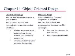
Chapter 11: The Object-Oriented Approach to Design: Use Case Realization. Systems Analysis and Design in a Changing World, Fourth Edition. Learning Objectives. Explain the purpose and objectives of object-oriented design Develop design class diagrams

E N D
Chapter 11:The Object-Oriented Approach to Design: Use Case Realization Systems Analysis and Design in a Changing World, Fourth Edition
Learning Objectives • Explain the purpose and objectives of object-oriented design • Develop design class diagrams • Develop interaction diagrams based on the principles of object responsibility and use case controllers Systems Analysis and Design in a Changing World, 4th Edition
Learning Objectives (continued) • Develop detailed sequence diagrams as the core process in systems design • Develop communication diagrams as part of systems design • Document the architectural design using package diagrams Systems Analysis and Design in a Changing World, 4th Edition
Overview • Primary focus of this chapter is how to develop detailed object-oriented design models • Programmers use models to code the system • Two most important models are design class diagrams and interaction diagrams (sequence diagrams and communication diagrams) • Class diagrams are developed for domain, view, and data access layers • Interaction diagrams extend system sequence diagrams Systems Analysis and Design in a Changing World, 4th Edition
Object-Oriented Design—The Bridge Between Analysis and Programming • Bridge between users’ requirements and new system’s programming • Object-oriented design is process by which detailed object-oriented models are built • Programmers use design to write code and test new system • User interface, network, controls, security, and database require design tasks and models Systems Analysis and Design in a Changing World, 4th Edition
Overview of Object-Oriented Programs • Set of objects that cooperate to accomplish result • Object contains program logic and necessary attributes in a single unit • Objects send each other messages and collaborate to support functions of main program • OO systems designer provides detail for programmers • Design class diagrams, interaction diagrams, and some state machine diagrams Systems Analysis and Design in a Changing World, 4th Edition
Object-Oriented Three-Layer Program Systems Analysis and Design in a Changing World, 4th Edition
Sequence Diagram for Updating Student (Figure 11-2) Systems Analysis and Design in a Changing World, 4th Edition
Student Class Examples for the Domain Class and the Design Class Diagrams (Figure 11-3) Systems Analysis and Design in a Changing World, 4th Edition
Example Class Definition in Java for Student Class(Figure 11-4a) Systems Analysis and Design in a Changing World, 4th Edition
Object-Oriented Design Processes and Models • Diagrams developed for analysis/requirements • Use case diagrams, use case descriptions and activity diagrams, domain model class diagrams, and system sequence diagrams • Diagrams developed for design • Interaction diagrams and package diagrams • Design class diagrams – include object-oriented classes, navigation between classes, attribute names, method names, and properties needed for programming Systems Analysis and Design in a Changing World, 4th Edition
Design Models with Their Respective Input Models(Figure 11-5) Systems Analysis and Design in a Changing World, 4th Edition
Iterative Process of OO Design—Design Steps (Figure 11-6) Realization of use case – specialization of all detailed system processing for each use case Systems Analysis and Design in a Changing World, 4th Edition
Design Classes, Interaction, and Design Process • Design class diagrams and detailed interaction diagrams • Use each other as inputs and are developed in parallel • First-cut design class diagram is based on domain model and system design principles • First-cut sequence diagram for use case is extended from system sequence diagram (SSD) • Shows interacting objects • Sequence diagram is completed layer by layer • Problem domain, data access, and view layers • Design class diagram is updated based on sequence diagram Systems Analysis and Design in a Changing World, 4th Edition
Design Class Symbols • UML does not distinguish between design class notation and domain model notation • Domain model class diagram shows conceptual classes in users’ work environment • Design class diagram specifically defines software classes • UML uses stereotype notation to categorize a model element by its characteristics Systems Analysis and Design in a Changing World, 4th Edition
Standard Stereotypes Found in Design Models (Figure 11-7) Systems Analysis and Design in a Changing World, 4th Edition
Standard Design Classes • Entity – design identifier for problem domain class • Persistent class – exists after system is shut down • Control – mediates between boundary and entity classes, between the view layer and domain layer • Boundary – designed to live on system’s automation boundary, touched by users • User interface and windows classes • Data access – retrieves data from and sends data to database Systems Analysis and Design in a Changing World, 4th Edition
Navigation Visibility • A design principle in which one object has reference to another object • Can interact with other object by sending messages Systems Analysis and Design in a Changing World, 4th Edition
Design Class Notation • Name – class name and stereotype information • Attribute visibility (private or public) – attribute name, type-expression, initial-value, property • Method signature – information needed to invoke (or call) the method • Method visibility, method name, type-expression (return parameter), method parameter list (incoming arguments) • Overloaded method – method with same name but two or more different parameter lists • Class-level method – method associated with class instead of each object (static or shared method), denoted by an underline Systems Analysis and Design in a Changing World, 4th Edition
Notation Used to Define a Design Class (Figure 11-8) Systems Analysis and Design in a Changing World, 4th Edition
Student Design Class Example Systems Analysis and Design in a Changing World, 4th Edition
Developing the First-Cut Design Class Diagram • Extend domain model class diagram • Elaborate attributes with type and initial value information • Detailed design proceeds use case-by-use case • Interaction diagrams implement navigation • Navigation arrows are updated to be consistent • Method signatures are added to each class Systems Analysis and Design in a Changing World, 4th Edition
Developing First-Cut Design Class Diagram (Continued) • Choose classes involved with the use case • Add use case controller • Elaborate attributes • Visibility, type-expression, initial-value, property • Establish first-cut navigation visibility • One-to-many relationships usually navigated from superior to subordinate • Mandatory relationships usually navigated from independent to dependent • When an object needs information from another object, navigation arrow points to the object itself or to its parent in hierarchy • Navigation can be in both directions (arrows bidirectional) Systems Analysis and Design in a Changing World, 4th Edition
Start with Domain Model Class Diagram Systems Analysis and Design in a Changing World, 4th Edition
First-Cut RMO Design Class Diagram for Look Up Item Availability Use Case (Figure 11-11) Systems Analysis and Design in a Changing World, 4th Edition
Design Patterns and the Use Case Controller • Design pattern • A standard solution template to a design requirement that facilitates the use of good design principles • Use case controller pattern • Design requirement is to identify which problem domain class should receive input messages from the user interface for a use case • Solution is to choose a class to serve as a collection point for all incoming messages for the use case. Controller acts as intermediary between outside world and internal system • Artifact – a class invented by a system designer to handle a needed system function, such as a controller class Systems Analysis and Design in a Changing World, 4th Edition
Some Fundamental Design Principles • Encapsulation – each object is self-contained unit that includes data and methods that access data • Object reuse – designers often reuse same classes for windows components • Information hiding –data associated with object is not visible to outside world • Protection from variations – parts of a system that are unlikely to change are segregated from those that will • Indirection –an intermediate class is placed between two classes to decouple them but still link them Systems Analysis and Design in a Changing World, 4th Edition
Some Fundamental Design Principles (Continued) • Coupling – qualitative measure of how closely classes in a design class diagram are linked • Number of navigation arrows in design class diagram or messages in a sequence diagram • Loosely coupled – system is easier to understand and maintain • Cohesion – qualitative measure of consistency of functions within a single class • Separation of responsibility – divide low cohesive class into several highly cohesive classes • Highly cohesive – system is easier to understand and maintain and reuse is more likely Systems Analysis and Design in a Changing World, 4th Edition
Realizing Use Cases and Defining Methods —Designing with Sequence Diagrams • Realization of use case done through interaction diagram development • Determine what objects collaborate by sending messages to each other to carry out use case • Sequence diagrams and communication diagrams represent results of design decisions • Use well-established design principles such as coupling, cohesion, separation of responsibilities Systems Analysis and Design in a Changing World, 4th Edition
Object Responsibility • Objects are responsible for system processing • Responsibilities include knowing and doing • Knowing about object’s own data and other classes of objects with which it collaborates to carry out use cases • Doing activities to assist in execution of use case • Receive and process messages • Instantiate, or create, new objects required to complete use case • Design means assigning responsibility to the appropriate classes based on design principles and using design patterns Systems Analysis and Design in a Changing World, 4th Edition
Designing with Sequence Diagrams • Sequence diagrams used to explain object interactions and document design decisions • Document inputs to and outputs from system for single use case or scenario • Capture interactions between system and external world as represented by actors • Inputs are messages from actor to system • Outputs are return messages showing data Systems Analysis and Design in a Changing World, 4th Edition
Annotated System Sequence Diagram (SSD) for the Look Up Item Availability Use Case (from Chapter 7) Systems Analysis and Design in a Changing World, 4th Edition
First-Cut Sequence Diagram • Start with elements from SSD • Replace :System object with use case controller • Add other objects to be included in use case • Select input message from the use case • Add all objects that must collaborate • Determine other messages to be sent • Which object is source and destination of each message? Systems Analysis and Design in a Changing World, 4th Edition
Objects included in Look Up Item Availability Systems Analysis and Design in a Changing World, 4th Edition
Guidelines for Sequence Diagram Development for Use Case • Take each input message and determine internal messages that result from that input • For that message, determine its objective • Needed information, class destination, class source, and objects created as a result • Double check for all required classes • Flesh out components for each message • Iteration, guard-condition, passed parameters, return values Systems Analysis and Design in a Changing World, 4th Edition
First-Cut Sequence Diagram for the Look Up Item Availability Use Case (Figure 11-14) Systems Analysis and Design in a Changing World, 4th Edition
Assumptions About First-Cut Sequence Diagram • Perfect technology assumption • Don’t include system controls like login/logout (yet) • Perfect memory assumption • Don’t worry about object persistence (yet) • Assume objects are in memory ready to work • Perfect solution assumption • Don’t worry about exception conditions (yet) • Assume happy path/no problems solution Systems Analysis and Design in a Changing World, 4th Edition
Maintain Product Information Use Case— Start with SSD Systems Analysis and Design in a Changing World, 4th Edition
Add Controller and Identify Domain Classes and Navigation Visibility Systems Analysis and Design in a Changing World, 4th Edition
Replace :System Object in SSD with Controller and Domain Objects (Figure 11-17) Systems Analysis and Design in a Changing World, 4th Edition
First-Cut Sequence Diagram for Maintain Product Information Use Case (Figure 11-18) Systems Analysis and Design in a Changing World, 4th Edition
Developing a Multilayer Design • First-cut sequence diagram – use case controller plus classes in domain layer • Add data access layer – design for data access classes for separate database interaction • No more perfect memory assumption • Separation of responsibilities • Add view layer – design for user-interface classes • Forms added as windows classes to sequence diagram between actor and controller Systems Analysis and Design in a Changing World, 4th Edition
Approaches to Data Access Layer Systems Analysis and Design in a Changing World, 4th Edition
Approaches to Data Access Layer (Continued) • Create data access class for each domain class • CustomerDA added for Customer • Database connection statements and SQL statements separated into data access class. Domain classes do not have to know about the database design or implementation • Approach (a) – controller instantiates new customer aC; new instance asks DA class to populate its attributes reading from the database • Approach (b) – controller asks DA class to instantiate new customer aC; DA class reads database and passes values to customer constructor • Two following examples use this approach Systems Analysis and Design in a Changing World, 4th Edition
Adding Data Access Layer for Look Up Item Availability Use Case (Figure 11-20) Systems Analysis and Design in a Changing World, 4th Edition
Adding Data Access Layer for Maintain Product Information Use Case (Figure 11-21) Systems Analysis and Design in a Changing World, 4th Edition
Designing the View Layer • Add GUI forms or Web pages between actor and controller for each use case • Minimize business logic attached to a form • Some use cases require only one form; some require multiple forms and dialog boxes • View layer design is focused on high-level sequence of forms/pages – the dialog • Details of interface design and HCI in Chapters 13 and 14 Systems Analysis and Design in a Changing World, 4th Edition
<<View>> ProductQuery Form Added for Look Up Item Availability Use Case Systems Analysis and Design in a Changing World, 4th Edition
Complete Look Up Item Availability Use Case with View Layer (Figure 11-22) Systems Analysis and Design in a Changing World, 4th Edition
ProductWindow and MsgWindow for Maintain Product Information Use Case Systems Analysis and Design in a Changing World, 4th Edition