PARTIAL RECONFIGURATION DESIGN
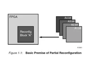
PARTIAL RECONFIGURATION DESIGN. Partial Reconfiguration. Partial Reconfiguration : Ability to reconfigure a portion of the FPGA while the remainder of the design is still operational Application areas: In-the-field hardware upgrades and updates to remote sites Runtime reconfiguration (RTR)

PARTIAL RECONFIGURATION DESIGN
E N D
Presentation Transcript
Partial Reconfiguration • Partial Reconfiguration : • Ability to reconfigure a portion of the FPGA while the remainder of the design is still operational • Application areas: • In-the-field hardware upgrades and updates to remote sites • Runtime reconfiguration (RTR) • Swap in/out tasks • Adaptive hardware algorithms (EHW) • Benefits: • Reduced device count • Reduced power consumption • More efficient use of available board space • Very few devices in the market: • Xilinx 6200: obsolete • Xilinx Virtex
Partial Reconfiguration • Design Flows: • JBits approach • For few old devices • Modular Design Flow • Difference-Based Approach
Partial Reconfiguration • Bitstream: • Configuration data which can be downloaded into the device via the configuration port • Packet: • Fragment of the complete bitstream sent to the device to reconfigure the needed part of the device • Configuration memory: • Part of the processor memory dedicated for reconfiguration data • Dirty packets: • Marked packets showing the changes made between the last configuration and the present one
CLB Virtex Devices • Partial reconfiguration in Virtex: • Frames: • Smallest unit of reconfiguration. • Frames in Xilinx devices: • Virtex, Virtex II, Virtex II-Pro: • The whole column. • Virtex 4, Virtex 5 • Only a complete tile. • Different in various devices: Logical shared memory TASK 2 TASK 1 Height Width [Banerjee07]
Bitstream Manipulation with JBits • JBits: • A tool to allow the end user to set the content of the LUT and make connections inside the FPGA “directly” • by changing reconfiguration data. • JBits API: • A set of java classes, methods: • to set the LUT-values • to define the interconnections • to read back the content of the FPGA currently in use.
JBits Methods set(row, col, SliceNumber, Type, value) • Sets LUT of type F or G in slice 0 or 1 in CLB at (row, col) by array value • value: 16 entries for 4LUT connect(outpin, inpin) • Connects the pin outpin to the pin inpin anywhere inside the FPGA (terminals of CLB)
JBits Methods • JBits IP Cores: • Hundreds of predefine cores: • adders, • subtractors, • multipliers, • CORDIC Processor, • encoder and decoders, • network modules • Can directly be used in designs • Can also be combined to generate more complex cores.
Approaches to PR • Partial Reconfiguration in Xilinx Devices: • Module-based PR: • Implement any single component separately. • Constrain components to be placed at a given location. • Complete bitstream is finally built as the sum of all partial bitstreams. • Difference-based PR: • Implement the complete bitstreams separately. • Implement fix parts + reconfigurable parts with components constrained at the same location in all the bitstreams. • Compute the difference of two bitstreams to obtain the partial bitstream needed to move from one configuration to the next one.
Module-Based PR • Reconfigurable Module (RM): • Distinct portions of an FPGA design to be reconfigured while the rest of the device remains in active operation. • Properties of RMs: • RM’s height is the full height of the device. • or the height of a frame in Virtex 4, 5, 6 • RM’s width: min = 4 slices, max = full-device width (in four-slice increments) • Horizontal placement must always be on a four-slice boundary; the leftmost placement being x = 0, 4, 8, … • All logic resources encompassed by the width of the module are considered part of the RM's bitstream "frame“ • This includes slices, TBUFs, block RAMs, multipliers, IOBs, and most importantly, all routing resources. • Clocking logic (BUFGMUX, CLKIOBs) is always separate from the reconfigurable module. • Clocks have separate bitstream frames.
Module-Based PR • Properties of RMs: • IOBs immediately above the top edge and below the bottom edge of an RM are part of the specific RM’s resources. • If an RM occupies the leftmost/rightmost slice column, all IOBs on the specific edge are part of the specific RM’s resources. • RMs communicate with other modules (both fixed and reconfigurable) by using a special bus macro. • The implementation must be designed so that the static portions of the design do not rely on the state of the module under reconfiguration while reconfiguration is taking place. • The implementation should ensure proper operation of the design during the reconfiguration process. • Explicit handshaking (module ready/not-ready) logic may be required. • The state of the storage elements inside the RM are preserved during and after the reconfiguration process. • Designs can take advantage of this fact to utilize "prior state" information after a new configuration is loaded.
Module-Based PR • Initially developed to allow several engineers to cooperatively work on the same project. • Procedure: • Project leader: • Identifies the components of the whole project, • Estimates the amount of resources consumed by each component, • Defines locations for the components on the device • Engineers: • develop the single parts independently.
Modular Design Flow • Steps: • Design entry and synthesis, • Initial budgeting, • Active implementation • Assembly
Bus Macros in Xilinx FPGAs • Problem in partial reconfiguration: • The resulting application may not work if the signals connecting the fix and dynamic part are not using the same paths in the two configurations. • Solution: • Bus macro provides fix communication channels, which can be used by reconfigurable module. • tri-state lines • not affected by the reconfiguration
Module-Based PR • Module-Based PR Flow: • Bus Macrosguarantee fixed communication channels among RMs and the fixed part. • One must ensure that signals will not be routed on the wrong paths after the reconfiguration. • Routing resources used for such inter-module signals must not change when a module is reconfigured. • By JBits, you must route manually again!
Bus Macro • Bus macro: • The HDL code should ensure that any reconfigurable module signal that is used to communicate with another module does so only by first passing through a bus macro. • Each bus macro provides for 4-bits of inter-module communication. • if A communicates via 32 bits to B, then eight (32/4) bus macros will need to be instantiated.
Automatic Bus Macro Placement for Partially Reconfigurable FPGA Designs, Jeffrey M. Carver, Richard N. Pittman, FPGA09
Difference-Based Partial Reconfiguration • Useful for making small on-the-fly changes to design parameters such as logic equations, …. • Procedure: • Designer makes small logic changes using FPGA_Editor: • changing I/Os, • block RAM contents • LUT programming • muxs • flip-flop initialization and reset values • pull-ups or pull-downs on external pins • block RAM write modes • Changing any property or value that would impact routing is not recommended due to the risk of internal contention • Uses BitGen to generate a bitstream that programs only the difference between the two versions. • Very quick switching
Difference-Based Partial Reconfiguration • Viewing a block
Difference-Based Partial Reconfiguration • Change LUT equations
Difference-Based Partial Reconfiguration • Changing Block RAM Contents
Difference-Based Partial Reconfiguration • More details in [Eto07]
Direct Bitstream Manipulation in Virtex [Upegui05]
Direct Bitstream Manipulation in Virtex • Addressing LUT contents of a bitstream: • For Virtex family, XAPP151 describes detailed bitstream. • Virtex-II upward has not been documented • But LUT contents can be localized in configuration bitstream.
CLBs CLB: 4 slices 13 03 12 02 11 01 10 30 00 20
Frame Description (XC2V40) • Details in [Upegui05] Unknown functionality Unknown functionality
LUT Contents • In Virtex family: • LUT configurations are stored inverted: • 4-input AND function, 0111 1111 1111 1111 (7F FF) instead of 1000 0000 0000 0000 • Bit order is swapped in F-LUTs respective to G-LUTs: • in G-LUT: 7F FF • in F-LUT: FF FE • Benefits of direct manipulation: • E.g. evolving circuits in a very flexible way • Run-time reconfiguration
References • [Bobda07] Christophe Bobda, “Introduction to Reconfigurable Computing: Architectures, Algorithms and Applications,” Springer, 2007. • [Virtex-4] “Virtex-4 Configuration Guide,” http://www.xilinx.com. • [Lim02] Davin Lim and Mike Peattie, “Two Flows for Partial Reconfiguration,” XAPP290, v1, www.xilinx.com, 2002. • Module Based or Small Bit Manipulations • [Eto07] Emi Eto, “Difference-Based Partial Reconfiguration,” XAPP290, v2, www.xilinx.com, 2007. • [Upegui05] A. Upegui and E. Sanchez “Evolving hardware by dynamically reconfiguring Xilinx FPGAs,” Evolvable Systems: From Biology to Hardware, LNCS 3637, 2005.