Download
1 / 29
300 likes | 516 Vues
Run-Time FPGA Partial Reconfiguration for Image Processing Applications. Shaon Yousuf Ph.D. Student NSF CHREC Center, University of Florida Dr. Ann Gordon-Ross Assistant Professor of ECE NSF CHREC Center, University of Florida. Introduction.

E N D
Run-Time FPGA Partial Reconfiguration for Image Processing Applications Shaon Yousuf Ph.D. Student NSF CHREC Center, University of Florida Dr. Ann Gordon-Ross Assistant Professor of ECE NSF CHREC Center, University of Florida
Introduction • Run-time reconfiguration is an important feature in SRAM-based FPGAs that allows changes in functionality dynamically • Enables benefits such as flexibility, hardware reuse and reduced power consumption • Drawbacks of run-time reconfiguration • Entire fabric is reconfigured even for slight design changes • System execution stalls completely • Time to load a design onto the fabric from external memory (reconfiguration time) increases with bitstream size • Run-time reconfiguration is enhanced by run-time partial reconfiguration (PR) which mitigate these drawbacks Flexibility Designs loaded when required Hardware Reuse Current required design replaces old one on the same fabric Design A Design B Design C Design A Power Savings Design A, B, & C stored in external memory Configuration controller Design B Design C Design C Required Design A Required Design B Required External memory FPGA Fabric
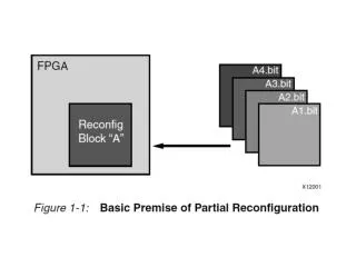
Module A ICAP Module B Central Controlling Agent Mem controller Module C Module D Partial Reconfiguration (PR) • PR allows the ability to reconfigure a portion of an FPGA dynamically by dividing the FPGA into two types of regions • Static region - contains static portion of the design (Static Modules) • Partially reconfigurable region (PRR) - loaded with a partial reconfiguration module (PRM) • PR benefits in addition to full reconfiguration benefits • Only reconfigured PRR is stalled while static region and other PPRs continue operating • Smaller bitstreams sizes • Reduced power consumption • Reduced memory requirements • Reduced time to reconfigure Static modules Reconfigurable Modules (PRMs) Module: A & B PRR 1 Modules: C & D Static modules Static region PRR 2 Example with 2 PRRs FPGA Fabric
Manual Steps PR Challenges and Motivations Xilinx PR Implementation Flow • PR is hard • Complicated design flow • Requires manual intervention and knowledge about target device • Can decrease system performance as compared to full reconfiguration if system design is not carefully considered • Despite these challenges, PR can potentially prove to be beneficial for certain application types • Resource savings, flexibility, power savings, etc. • Thus, it becomes necessary to explore PR for different application types • Provides valuable insights • Potentially ease PR for designers of similar application types HDL Design Description HDL Synthesis Set Design Constraints Timing/Placement Analysis Implement Static Design and PR Modules Merge Final Generated Bitstreams
Contribution • PR architecture benefits for a JPEG encoder system • JPEG encoder/decoder systems are a key enabling technology for low-power and high-performance image transmission for on-line satellite communication • The JPEG encoder PR architecture provides increased flexibility as compared to a non-PR architecture • Leveraging the JPEG encoder PR architecture we propose a PR architecture for a JPEG encoder/decoder (codec) system • The proposed PR codec architecture will provide significant benefits in terms of resource savings and power savings as well as flexibility • Study of the PR architecture of the JPEG systems can be adapted to realize potential benefits for similar applications types
JPEG Encoder/Decoder Process JPEG encoding process for color images is divided into four main steps Color Space Transformation - RGB to YCbCr Forward Discrete Cosine Transform (FDCT) Quantization Entropy Encoding 8x8 data block of each color component Table Specifications Table Specifications Compressed Image Data RGB to YCbCr Entropy Encoder FDCT Quantizer 6
JPEG Encoder/Decoder Process JPEG encoding process for color images is divided into four main steps Color Space Transformation - RGB to YCbCr Forward Discrete Cosine Transform (FDCT) Quantization Entropy Encoding JPEG decoder performs these steps in reverse Reconstructed 8x8 data block of each color component Table Specifications Table Specifications Compressed Image Data YCbCr to RGB Entropy Decoder IDCT Dequantizer 7
JPEG Encoder Architecture HOST DATA 8x8 Data blocks HOST PROG RAM Control Signals Host Interface MUX Control Signals Data Control Signals Header Generator H: 0xFF Pipeline Controller Buffer RGB2YCbCr & FDCT2D ZigZag Quantizer Run Length Encoder Huffman Encoder and Byte Stuffer Skipping ahead to when processing is almost done…… 8
JPEG Encoder Architecture 8x8 Data blocks HOST DATA HOST PROG RAM Control Signals Host Interface MUX Data Control Signals Control Signals Buffer Header Generator EOI : 0xFF Pipeline Controller RGB2YCbCr & FDCT2D ZigZag Quantizer Run Length Encoder Huffman Encoder and Byte Stuffer Encoding Complete! 9
JPEG Encoder PR Architecture • Pipeline controller module • Ability to replace with updated module • Ability to replace with different controller module HOST DATA HOST PROG RAM Control Signals Control Signals Host IF Data Byte Stuffer MUX Control Signals Buffer Pipeline Controller Header Generator RGB2YCbCr & FDCT2D ZigZag Quantizer Run Length Encoder Huffman Encoder
JPEG Encoder PR Architecture • RGB2YCbCr and FDCT module • Ability to replace with an updated module • Ability to skip color space transformation by replacing with a module that only does DCT • Ability to replace different DCT types HOST DATA HOST PROG RAM PR Region PR Module Control Signals Control Signals Host IF Data Byte Stuffer MUX Control Signals Buffer Pipeline Controller Header Generator RGB2YCbCr & FDCT2D ZigZag Quantizer Run Length Encoder Huffman Encoder 11
JPEG Encoder PR Architecture • Entropy encoder modules (Zigzag, Run length, Huffman, Header Generator, Byte Stuffer) • Ability to update each individual module • Ability to employ different entropy encoding schemes • Ability to replace Huffman code tables and update header accordingly HOST DATA HOST PROG RAM PR Region PR Module Control Signals Control Signals Host IF Data Byte Stuffer MUX Control Signals Buffer Pipeline Controller Header Generator RGB2YCbCr & FDCT2D ZigZag Quantizer Run Length Encoder Huffman Encoder 12
JPEG Encoder PR Architecture • Quantization Module • Ability to replace with an updated module • Ability to change quantization matrix tables to control image quality HOST DATA HOST PROG RAM PR Region PR Module Control Signals Control Signals Host IF Data Byte Stuffer MUX Control Signals Buffer Pipeline Controller Header Generator RGB2YCbCr & FDCT2D ZigZag Quantizer Run Length Encoder Huffman Encoder 13
JPEG Encoder PR Architecture • Advantages of JPEG Encoder PR Architecture • Provides flexibility by allowing the ability to replace different modules • More interesting benefits arise when the encoder architecture is combined with a decoder architecture HOST DATA HOST PROG RAM PR Region PR Module Control Signals Control Signals Host IF Data Byte Stuffer MUX Control Signals Buffer Pipeline Controller Header Generator RGB2YCbCr & FDCT2D ZigZag Quantizer Run Length Encoder Huffman Encoder 14
JPEG Codec PR Architecture HOST DATA PR Region RAM HOST PROG PR Module Control Signals MUX Control Signals Host IF Data Control Signals Byte Stuffer Buffer Decoder Pipeline Controller Encoder Pipeline Controller DEMUX Header Generator Reorder Dequantizer Run length decoder Huffman Decoder ZigZag Quantizer Run length Encoder Huffman Encoder YCbCr2RGB & IDCT2D RGB2YCbCr & FDCT2D 15
JPEG Codec PR Architecture Encoder Data Path Encoder Architecture HOST DATA PR Region RAM HOST PROG PR Module Control Signals MUX Control Signals Host IF Data Control Signals Byte Stuffer Buffer Decoder Pipeline Controller Encoder Pipeline Controller DEMUX Header Generator ZigZag Quantizer Run length Encoder Huffman Encoder RGB2YCbCr & FDCT2D 16
JPEG Codec PR Architecture Decoder Data Path Decoder Architecture HOST DATA PR Region RAM HOST PROG PR Module Control Signals MUX Control Signals Host IF Data Control Signals Byte Stuffer Byte Stripper Buffer Decoder Pipeline Controller Encoder Pipeline Controller DEMUX Header Decoder Header Generator Reorder Dequantizer Run Length Decoder Huffman Decoder YCbCr2RGB & IDCT2D 17
JPEG Codec PR Architecture Contd. • Benefits • Resource savings • Same hardware resources shared between encoder and decoder • Power savings • PR module bitstreams stored in memory and loaded on demand (decoding or encoding) as opposed to both occupying actual hardware resources • Increased flexibility • Encoder and decoder PR modules can be updated as needed or replaced with one of another type as per application requirements • Architecture limitations • For a PR module loaded into a particular region • The loaded PR module’s size and resource requirements (slices, FIFOs, BRAMs, DSPs) cannot exceed the maximum available in the PR region • PR module port connections, both incoming and outgoing, cannot exceed the PR regions maximum incoming and outgoing port connections, respectively 18
Experimental Setup • Software • Xilinx ISE 9.204 with PR patch 12 installed • Synthesize options • Optimization Goal - Speed • Optimization Effort - Normal • Hardware • Xilinx Virtex-4 LX60
Results – Architecture Specifications • Input image specifications • Color images only (3 components, RGB input) • Supported resolution 800x600 • JPEG Encoder system • JPEG baseline encoding JPEG ITU-T T.81 | ISO/IEC 10918-1 • Standard JFIF header v 1.01 automatic generation • Design operates above 100 MHz • Hardcoded Huffman tables and two programmable quantization tables, one for luminance and one for chrominance at 50% quality settings 50% quality reduced 100Mhz T H JPEG Encoder System 20
Results: JPEG Encoder PR Architecture Floorplan Quantizer Module Pipeline controller Module FDCT Module Huffman Encoder Module Zigzag Module Byte Stuffer Module Header Generation Module Run length Encoder Module 21
Results: Resource Requirements • JPEG Encoder Architecture • Total Slices = 5,531 • Total DSP48s = 9 • Total FIFO/RAMB16s = 27 • JPEG Encoder PR Architecture • Total Slices = 5,678 • Total DSP48s = 9 • Total FIFO/RAMB16s = 27 Slice Requirements 22
Results: Resource Requirements • JPEG Encoder Architecture • Total Slices = 5,531 • Total DSP48s = 9 • Total FIFO/RAMB16s = 27 • JPEG Encoder PR Architecture • Total Slices = 5,678 • Total DSP48s = 9 • Total FIFO/RAMB16s = 27 DSP48 Requirements 23
Results: Resource Requirements • JPEG Encoder Architecture • Total Slices = 5,531 • Total DSP48s = 9 • Total FIFO/RAMB16s = 27 • JPEG Encoder PR Architecture • Total Slices = 5,678 • Total DSP48s = 9 • Total FIFO/RAMB16s = 27 FIFO/RAMB16s Requirements 24
Results: PR vs Non PR Architectures • Encoder architecture slice requirement = 5531 • Predicted decoder architecture slice requirement ~ 5600 25
Results: PR vs Non-PR Architectures • Predicted total slice requirement for non-PR codec architecture ~ 11200 • Predicted PR codec architecture slice requirement ~ 6100 11200 Slices Slice Macro Overhead : 7% or 416 Slices 26
Results: PR vs Non-PR Architectures • Predicted total slice requirement for non-PR codec architecture ~ 11200 • Predicted PR codec architecture slice requirement ~ 6100 • Predicted resource savings from PR codec architecture = ((11200-6100) * 100)/11200 = 45%!! 45% Savings!! 27
Conclusions and Future Work • Conclusions • We created a JPEG encoder PR architecture for image encoding • The architecture provides increased flexibility and potential power savings with a slice macro overhead of only 4% • The architecture forms a base for a JPEG codec PR architecture • The JPEG codec architecture is predicted to benefit from increased flexibility and power savings as well as area savings as much as 45% relative to a non-PR codec architecture • Future Work • Complete proposed JPEG codec PR architecture • Extend work to development of PR architectures for MPEG/H.264 encoder and decoder systems
QUESTIONS? This work was supported in part by the I/UCRC Program of the National Science Foundation under Grant No. EEC-0642422. We also gratefully acknowledge tools provided by Xilinx.