Download
1 / 29
290 likes | 381 Vues
Detailed report on the Steigerwald results reported in SPIN 2000 and JLab measurements in June 2012. Agreement levels, target thickness significance, vendor claims, electron beam conditions, and momentum distributions explored.

E N D
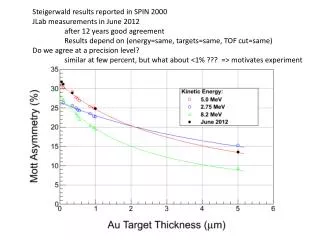
Steigerwald results reported in SPIN 2000 JLab measurements in June 2012 after 12 years good agreement Results depend on (energy=same, targets=same, TOF cut=same) Do we agree at a precision level? similar at few percent, but what about <1% ??? => motivates experiment
Significance of target thickness Our vendor Lebow claims 10% absolute and 2% relative to foil dS(d)/S(d) = (-b * ad) / ( 1+ ad), where b = dd/d
dS(d)/S(d) = (-b * ad) / ( 1+ ad), where b = dd/d 0 – 10 mm 0 – 1 mm b 2% 4% 6% 8% 10%
Thermionic SEM images : • encouraging, consistent with vendor claim • in future will co-deposit onto Si wafer • employ field emission SEM (1 nm = 0.001 mm resolution)
105 e- pass 1um Au target & illuminate 1” thick dump : Cu, Al, C, Be Units are millimeters and MeV/c unless stated Electrons are RED andPhotons are GREEN unless stated Particles entering target (z = -1) • Pencil Beam • Pz = 5.5 • Px = Py = 0 • sx = sy = 0.5 • spx = spy = 0 Particles exiting target (z = 1, R=12.7)
Electron and photon spatial distributions in front of dump (going to or coming from)
1 mm upstream of Dump Copper (Z=29) Pz>0 Pz<0
1 mm upstream of Dump Aluminum (Z=13) Pz>0 Pz<0
1 mm upstream of Dump Carbon (Z=6) Pz>0 Pz<0
1 mm upstream of Dump Beryllium (Z=4) Pz>0 Pz<0
Electron and photon momentum distributions in front of dump returning toward target
Electrons with Pz < 0 1 mm upstream of Dump Cut: Pz < 0 Cu Al Number of Electrons C Be Total Momentum [MeV/c]
Photons with Pz < 0 1 mm upstream of Dump Al Z=13 Cu Z=29 Number of photons Number of photons Total Momentum [MeV/c] Total Momentum [MeV/c] C Z=6 Be Z=4 Number of photons Number of photons Total Momentum [MeV/c] Total Momentum [MeV/c]
Electron and photon spatial distributions exiting downstream of dump
Pz > 0 (no events with Pz < 0) 1 mm downstream of Dump Al Z=13 (69 e-) Cu Z=29 (37 e-) C Z=6 (21 e-) Be Z=4 (17 e-) radial edge of Dump
Electrons and Photons traversing surfaces about 1mm outside of a 1” dump flange • upstream means returning from dump • downstream means exiting dump • sidewall means exiting OD surface Photons total downstream Electrons upstream total upstream sidewall sidewall downstream
So, what reaches the target plane ? Assuming “illuminous dump” is uniform in backward 2pi then 324cm2 detector plane 1.8m from dump represents 1.5% angular acceptance. Testing for Aluminum… 1.5% * 1644 = 25 1.5% * 10084 = 151 target
Summary • C or Be are similar, both better than Al and by • about 3-4 for e- • about 2-3 for photons • Cu is better absorber of gamma by factor of about 2 • Could be a good backing material, but should not be proud in chamber • Simulation rates fine for characterizing dump; poor for back-illuminate target • 105 target events (per second) is 16nA or 106 overnight still low stat • Target – Dump distance is about 1.8m so need to bias simulation • More realistic model will be helpful • Use a reasonable e- beam distribution • Verify multiple-scattering distribution • Include dump dipole • About 90% of e- reach the dump, so more careful detail on surfaces • Figure out how to integrate deposited energy using G4Beamline
Mott Progress Report on Schedule, Target Ladder and Beam Dump Plate Joe Grames August 14
Schedule • Present work schedule • Sept 28 HCO begins • Nov 1 Mott tunnel work complete • Nov 4 2K recovery begins • Nov 8 Mott commissioning plan ready • Nov 9 HCO ends • Nov 9 Injector setup begins • Nov 11 2K recovery ends • Nov 11 Pulsed beam to FC1 • Nov 16 Pulsed beam to FC2 • Nov 16 Mott ready for beam • Nov 21 Pulsed beam to INJ spectrometer • Nov 24 Pulsed beam to 0R dump (end of injector) • Nov 28 Run through Thanksgiving • Dec 18 1-pass pulsed beam at 2.2 GeV • Dec 20 Winter shutdown • Feb 5 ACC-II begins • May 7 ACC-II ends
Target Ladder • Budget approved for new target ladder parts and assembly. • Gears and fixture plate for precision position control designed and ordered • STAC-5 stepper motor controller software written and testing = good • Target ladder (0.16”) should be ordered today • Viewer machining and adapter plate requirements known, yet incomplete
Dump Plate : motivation to reduce backscatter “…angular distribution of backscattered electrons and the backscattering coefficient were measured for Cu, Ag, and Au targets of various thicknesses at the incident energy of 6.08 MeV, and for Be, C, Al, Cu, Ag, Au, and U targets of effectively semi-infinite thickness in the energy range 3.24-14.1 MeV.” From Leo
Dump Plate : motivation to reduce backscatter From same paper, angular distributions for semi-infinite thickness targets.
Dump Plate : energy loss 200keV – 8MeV energy loss is nearly all collisional at 1.6 MeV-cm2/g
Dump Plate : worst case thermal distribution I asked Dave Meekins if he would givs us a first pass look at thermal distribution given uniform energy loss in volume (beam radius * E/(dE/dx).