ITER Cryogenic System
ITER CODAC Colloquium 27 th -28th October, 2008 Barcelona, SPAIN. ITER Cryogenic System. Manel Sanmartí, CIEMAT-F4E Plants DIvision, ITER Department. Outline. ITER cryogenic requirements ITER CRYO project frame ITER cryogenic system Cryo controls and instrumentation Conclusions.

ITER Cryogenic System
E N D
Presentation Transcript
ITER CODAC Colloquium 27th-28th October, 2008 Barcelona, SPAIN ITER Cryogenic System Manel Sanmartí, CIEMAT-F4E Plants DIvision, ITER Department
Outline • ITER cryogenic requirements • ITER CRYO project frame • ITER cryogenic system • Cryo controls and instrumentation • Conclusions
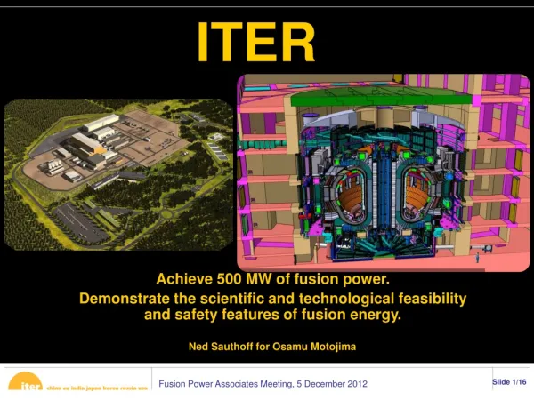
Main duties • Basic: • Cool-down of the cryostat and torus cryopumps • Gradual cool-down and filling of the magnet system and the 80 K thermal shield in about one month • Cool-down of the NB cryopumps, pellet units and gyrotrons • Maintain magnets and cryopumps at nominal temperatures over a wide range of operating modes with pulsed heat loads due to nuclear heating and magnetic field variations • Accommodate periodic regeneration of cryopumps • Accommodate resistive transitions and fast discharges of the magnets and recover from them in few days • Additional • Ensure high flexibility and reliability • Low maintenance
Cryogenic capacity & loads LHe cryoplant: 65 kW equivalent @ 4.5 K Cooling of the superconducting magnet system: 39 kW @ 4.2 K Cooling of HTS current leads: 150 g/s GHe at 50 K Cooling of cryo-pumps with high regeneration frequency: 6.5 kW @ 4.5 K and 70 g/s of LHe liquefaction Small users: 1 kW @ 4.5 K (Gyrotron) LN2 cryoplant: 1300 kW @ 80 K Thermal shielding: up to 800 kW @ 80 K during chamber baking LHe cryoplant pre-cooling: up to 280 kW @ 80 K during normal operation HTS 50 K extra cooling power: up to 180 kW @ 80 K during normal operation Helium inventory: 24 t
Magnets Pulsed Head Load Dynamics: 30W/s Amplitude: 12kW Repetition rate: 1800 sec
Operation scenarios • Uninterrupted operation in order to maximize machine availability • The tokamak will be operated during two 8-hour shifts • The third shift will be used to recover nominal cryogenic conditions, for short interventions and to regenerate the cryopumps up to 470 K • The large dynamic loads prevent full redundancy but allow continuous and uninterrupted operation without plasma • Short maintenance periods of few days every two weeks • Major shutdowns every 16 months • RAMI analysis to improve the design and requirements for spares
Technical variants • Analysis of technical variants compatible with the requirements and basic design principles are presently under study • Simplification of the layout and improvement of performances, reliability and availability or reduction of investment and operation costs • Review and update of heat loads • Large dynamic loads handling • Pulse mitigation by temporary by-pass of the structure load • Use of liquid helium storage buffering and complex process control • Helium management and cold quench tank temperature level • Optimal size, number of cold boxes and parallel operation (flow sharing) • Thermodynamic cycle optimization for the refrigerators • Developments of technology and engineering solutions for key components • Example: SHe circulating pumps and heat exchangers
Outline • ITER cryogenic requirements • ITER CRYO project frame • ITER cryogenic system • Few thoughts on control and instrumentation • Conclusions
The ITER CRYO project frame • Cryoplants system: helium refrigerators, LN2 and 80K loop system, ancillary equipment (warm/cold/liquid tanks, recovery & purification systems) • Cryodistribution system: main distribution boxes with cold circulating pumps and cold compressors, cryolines from cryoplant building and inside tokamak complex • Cryoplant procurement packages are based on functional specs and include manufacturing, delivery, installation & on-site individual sub-package acceptance test
Outline • ITER cryogenic requirements • ITER CRYO project frame • ITER cryogenic system • Few thoughts on control and instrumentation • Conclusions
ITER Cryoplant System Cryodistribution
Cryoplant architecture Pictures courtesy of CERN
Cryoplant layout option 1 80 K He loop Unloading area LN2 plant Instrumentation (control) room Power supply Room for power supply Unloading area Option 1 – LN2 plant and boxes of 80 K helium loop are located at outdoor area
ITER Cryodistribution System Cryodistribution
ITER Cryodistribution system 2 CVBs Cryostat 4 CVBs NB 8 CVBs Torus >50 Cold Boxes, 3 km of cryolines, 4500 components Coming From cryoplant CTCB ACB STR ACB PF ACB TF ACB CS ACB Cryopumps 25000 LHe tank Different levels
Outline • ITER cryogenic requirements • ITER CRYO project frame • ITER cryogenic system • Controls and instrumentation for cryogenics • As personal views this presentation does not necessarily reflect those from other involved parties (IO and IN DA) • Conclusions
Instrumentation requirements • Cryogenic instrumentation (industrial process/plants) • Pressure (1-200b, mbar, vacuum), Temperature (300-3.7K), Flow (warm/cold; 2-2000 g/s), • Gas quality & impurities (N2/H20/CxHy-ppm) • Actuators: Control & Pneumatic Valves, Quench valves (mech/PV), Heaters, Motors (On/Off, speed control) • Switches (safety interlocks) • Cryoplants • Installed redundancy for “inner” instrumentation Cold Boxes • Specific components like turbines (speed sensor, gas impurities) • Cryoditribution • Sub-atmospheric circuits (helium guard) • Speed/Freq. controllers for circulators/cold comp. • High magnetic fields and radiation environment • Accessibility constrains (operation scenarios) • Installed redundancy for “inner” instrumentation ACB
Control requirements • Cryoplants • Modular individual control sub-systems • Commissioning (staged, acceptance) • Operation scenarios • Dedicated PLC for critical components by suppliers: turbines • Cryoditribution • High magnetic fields and radiation environment • Accessibility constrains (operation scenarios) • Dedicated PLC for critical components by suppliers: cold circulators, cold comp. • Master control system • Cryo Integrated control system (IN, IO, EU) • General/individual data/interlocks exchange with other WBS (magnets, TS, cryopumps) • Machine interface (CODAC) • Standardization: hardware and software • Flexibility and “accessibility” during commissioning and first years of operation • Logging and post-mortem system for data/event analysis • Quality control (software updates, modifications) • Cryo and Central control room
Cryoplant control architecture? Data Servers EWS [1..x] Ethernet OWS [1..x]
Cryoplant control architecture? FIELD BUS networks TT, PT, LT, FT, TS, PS, LS, FS CV, PV, EH, EM OWS [1..x] EWS [1..x] Data Servers Ethernet Storage LHe CP1 LHe CP2 LHe CP3 Recup & Purif. 80K Loop 1&2 LHe CB1 LHe CB2 LHe CB3 CTCB LN2_1 LN2_2
Cryodistribution architecture? EWS [1..x] OWS [1..x] Data Servers Ethernet
Cryodistribution architecture? FIELD BUS networks TT, PT, LT, FT, TS, PS, LS, FS CV, PV, EH, EM EWS [1..x] OWS [1..x] Data Servers Ethernet Str. ACB PF ACB TF ACB CS ACB Cryopumps ACB Accessibility constrains High magnetic field High radiation enviroment
Conclusions • Cryogenics is a large industrial plant system • Instrumentation and controls requirements are well understood and identified • Controls architecture not yet defined • RAMI analysis and other projects experience to be used • Integration with clients (magnets, cryopumps, TS, others) • Radiation and high magnetic fields impact on cryodistribution instrumentation and electronics has to be validated • Standardization and integration of all cryogenics sub-systems is mandatory • Hardware (I&C) and software • To be defined before PA by involved parties • Common strategy and standard to be defined by all involved parties (IO, IN DA & F4E) before PA
THANK YOU!! Manel.Sanmarti@f4e.europa.eu