Download
1 / 18
180 likes | 333 Vues
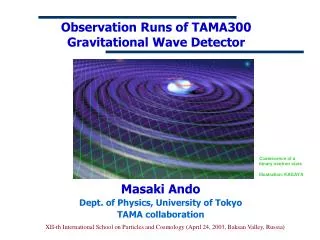
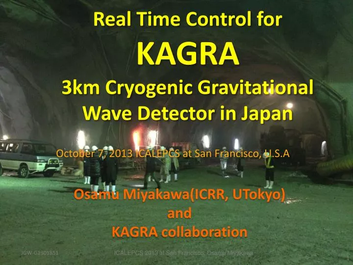
Real Time Control for KAGRA 3km Cryogenic Gravitational Wave Detector in Japan. October 7, 2013 ICALEPCS at San Francisco, U.S.A. Osamu Miyakawa(ICRR, UTokyo ) a nd KAGRA collaboration . Gravitational wave.

E N D
Real Time Control forKAGRA3km Cryogenic GravitationalWave Detector in Japan October 7, 2013 ICALEPCS at San Francisco, U.S.A Osamu Miyakawa(ICRR, UTokyo) and KAGRA collaboration ICALEPCS 2013 at San Francisco, Osamu Miyakawa
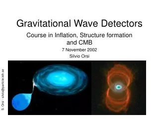
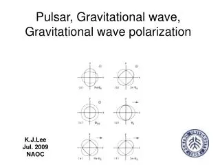
Gravitational wave Einstein’s Theory: information carried by gravitational radiation at the speed of light Gravitational waves! Coalescing compact binaries (neutron stars, black holes) Non-axi-symmetric supernova collapse Non-axi-symmetric pulsar (rotating, beaming neutron star) ICALEPCS 2013 at San Francisco, Osamu Miyakawa
Detection of gravitational wave using laser interferometer GWs move mirrors differentially. We measure the distance between mirrors using fringe of light. Expected length change by GW :~1x10-19m Mirror Mirror Lens Beam Splitter Fringe Screen Laser ICALEPCS 2013 at San Francisco, Osamu Miyakawa
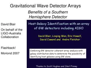
KAGRA Network of GW detectors GEO-HF 3km, underground LIGO-Indiain proposal 600m LIGO Hanford Advanced-Virgo 4km LIGO Livingston 3km 4km LIGO-Australia in proposal
Location of KAGRA • Underground Kamioka mine, Gifu prefecture. • ~250km away from Tokyo. • ~40km away from Japan sea. • This area is being used as cosmic ray observatories. Kamland XMASS Super Kamiokande CLIO KAGRA 3km Kamioka 250km Tokyo
KAGRA tunnel entrance(New Atotsu) 春(Spring) 冬(Winter) ④ ICALEPCS 2013 at San Francisco, Osamu Miyakawa
Laser room X arm Y arm ~80% of tunnel Done ④ Center room
Low temperature operation at KAGRA to reduce thermal distortion Inside radiation shield Cryostat construction and test Polished sapphire crystal of 200-mm diameter
Development of optical configurations Michelson interferometer (MI) Fabry-Perot MI (FPMI) Power recycling (PRFPMI) Dual recycling (DRFPMI) Control Keep dark condition at detection port to reduce shot noise • To keep interferometer being operated, we need • Very Low Noise Control all the time • Position: ~10DOFs • Angle: ~20DOFs • Others: ~100DOFs Longer light path using Fabry-Perot cavities Control Control CLIO Control Higher laser power by a power recycling mirror at laser port Control Control Enhance the GW signals by a signal recycling mirror at the dark port Control Control Control Control KAGRA, aLIGO, aVIRGO Control Control TAMA, LIGO , VIRGO Control
KAGRA control network design GPS antenna Remote Control room Metal cable Fiber cable Outside Timing master Client workstations Front room Mine Severs Circuit General network TCP/IP: EPICS, NFS, network boot Circuit DAQ network GW data: huge amount, low latency DAC Long RFM network BO RT control signal: very low latency ADC BO BO BO ADC ADC ADC DAC DAC DAC Short RFM network RT control signal: very low latency X end Computercenter Timing network Timing slave Timing slave Timing slave Timing slave Data storage Y end Real-time PCs 3km Centerroom ICALEPCS 2013 at San Francisco, Osamu Miyakawa
Rack layout for initial setup Real time PC test for End area Real time PC test for Center area Network for Kamiokabuiding Network for front-room in mine DAQ servers, storages Will be expanded when going to mine ICALEPCS 2013 at San Francisco, Osamu Miyakawa
Real time model on Matlab, Simulink Feedback filter Sensor Input Matrix Actuator 6DOF output signal 6DOF input signal Output Matrix Whitening/dewhitening Switch Global control ICALEPCS 2013 at San Francisco, Osamu Miyakawa
Generated C source of Real Time code from GUI Actual control signals(filter bank, matrix,trigger, linearization etc.)will be generated automatically when building real time modules. . . //Start of subsystem LSC ************************************************** // FILTER MODULE lsc_pox = filterModuleD(dsp_ptr,dspCoeff,LSC_POX,dWord[0][0],0); // FILTER MODULE lsc_poxfb = filterModuleD(dsp_ptr,dspCoeff,LSC_POXFB,dWord[0][1],0); . . for(ii=0;ii<1;ii++) { lsc_nxmtrx[1][ii] = pLocalEpics->ctr.LSC_NXMTRX[ii][0] * lsc_trx + pLocalEpics->ctr.LSC_NXMTRX[ii][1] * lsc_poxdc; } // Relational Operator lsc_operator = ((pLocalEpics->ctr.LSC_XTHRESH) <= (lsc_trx)); // DIVIDE if(lsc_nxmtrx[1][0] != 0.0) { lsc_divide = lsc_pox / lsc_nxmtrx[1][0]; } else{ lsc_divide = 0.0; } Running as kernel modules of Linux ICALEPCS 2013 at San Francisco, Osamu Miyakawa
MEMD screen -- GUI for EPICS -- Feedback filter Actuator Sensor Global control Offset control Input Matrix Output Matrix ICALEPCS 2013 at San Francisco, Osamu Miyakawa
Local control for Pre-Isolator Pre-Isolator Control ON Real Time PC Dataviewer (oscilloscope) MEDM Client WS ADC/DAC Anti Alias Anti Image DTT(FFT) Diagnosis on Mac through wireless LAN
DAQ items Timingreciever IO chassis (PCIe extension box) DAC 32ch ADC 16ch DAC Timing injection board ADC DIO 32ch Anti Alias filter 16ch Anti Imaging filter ICALEPCS 2013 at San Francisco, Osamu Miyakawa ~30 RT front-end PC ~30 Fiber connected PCIE extension chassis ~60 ADC (x32ch) : total ~2000ch ~40 DAC(x16ch): total ~500ch ~80 DO (x32ch): total ~2000ch
Network design for controls and DAQ RFM RT control signal: very low latency DAQ GW data: huge amount, low latency GPS antenna • Timing:Synchronization for all RT PC and ADC/DAC TCP/IP: EPICS, NFS, network boot Mozumi Entrance RFM RFM RFM DAQ DAQ DAQ Timing Timing Timing GW buildings at Kamioka TCP/IP TCP/IP TCP/IP New Atotsu Entrance Data Storage iKAGRA: 250TB bKAGRA: 1PB/year Remote control ICALEPCS 2013 at San Francisco, Osamu Miyakawa
Schedule bKAGRA iKAGRA • initial KAGRA • Room-temp. FPMI • Low laser power (10W ) • Simple seismic isolation • 10kg silica TM • baseline KAGRA • Cryogenic RSE • High laser power (180W) • Low frequency seismic isolation • 23kg sapphire TM • The project started in 2010 • Due to the March 11 earthquake (2011), budget implementation was delayed and whole the schedule shifted 1 year behind. • KAGRA will be in 2 stages: iKAGRA and bKAGRA ICALEPCS 2013 at San Francisco, Osamu Miyakawa