Download
1 / 10
110 likes | 320 Vues
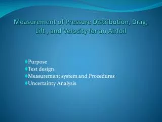
Measurement of Pressure Distribution and Lift for an Airfoil. Purpose Test design Measurement system and Procedures Uncertainty Analysis Data Analysis and Discussions . Purpose. Examine the surface pressure distribution Compute the lift force acting on the airfoil. Test Design.

E N D
Measurement of Pressure Distribution and Lift for an Airfoil Purpose Test design Measurement system and Procedures Uncertainty Analysis Data Analysis and Discussions
Purpose • Examine the surface pressure distribution • Compute the lift force acting on the airfoil
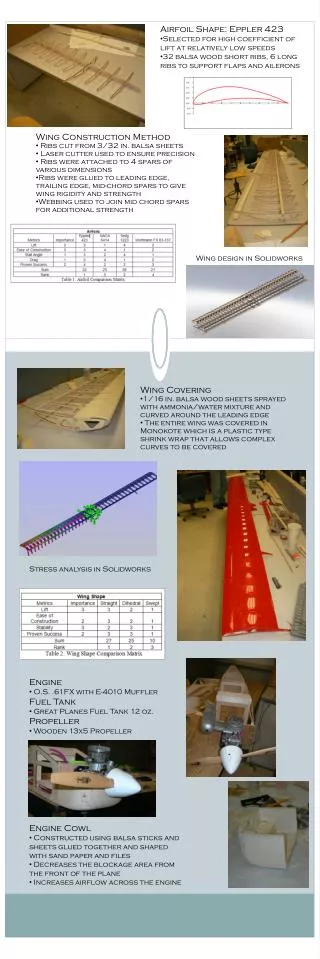
Test Design Airfoil(=airplane surface: as wing) is placed in test section of a wind tunnel where a flowing fluid (air) is operating. This airfoil is exposed to: • Forces acting normal to free stream = Lift • Forces acting parallel to free stream = Drag Only two dimensional airfoils are considered: Top of Airfoil: • The velocity of the flow is greater than the free-stream. • The pressure is negative Underside of Airfoil: • Velocity of the flow is less than the the free-stream. • The pressure is positive This pressure distribution contribute to the lift
Lift force The lift force L is determined by integration of the measured pressure distribution over the airfoil’s surface. It is expressed in a dimensionless form by the pressure coefficient Cp where pi = surface pressure measured, p = pressure in the free-stream U = free-stream velocity where r = air density ( temperature), pstagnation stagnation pr measured at the tip of pitot tube L = Lift force b = airfoil span c = airfoil chord
Pressure Distribution on the Airfoil In this experiment, the lift force, L on the Airfoil will be determined by integration of the measured pressure distribution over the Airfoil’s surface. The figure shows a typical pressure distribution on an Airfoil and its projection .
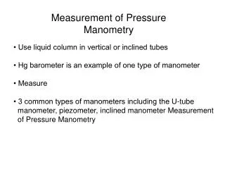
Protractor – angle of attack Resistance temperature detectors (RTD) Pitot static probe Scanning valve Pressure transducer (Validyne) Digital Voltmeter (DVM) Data Acquisition system
A virtual instrument(VI) = Lift is an ADAS is used to calculate the lift coefficient Data needed: Total # of points considered Observation point list Sampling Rate Settling Time Length of each Sample Conversion Coefficients Angle of attack ADAS
References plots with 6 different angles of attack: = 0 Group 1,2 = 4 Group 3,4 = 6 Group 5,6 = 8 Group 7,8 = 12 Group 9,10 = 14 Group 11 Reference Data