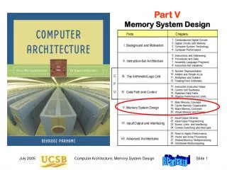
Part V Memory System Design
Part V Memory System Design. V Memory System Design. Design problem – We want a memory unit that: Can keep up with the CPU’s processing speed Has enough capacity for programs and data Is inexpensive, reliable, and energy-efficient. 17.6 The Need for a Memory Hierarchy.

Part V Memory System Design
E N D
Presentation Transcript
Part VMemory System Design Computer Architecture, Memory System Design
V Memory System Design • Design problem – We want a memory unit that: • Can keep up with the CPU’s processing speed • Has enough capacity for programs and data • Is inexpensive, reliable, and energy-efficient Computer Architecture, Memory System Design
17.6 The Need for a Memory Hierarchy The widening speed gap between CPU and main memory Processor operations take of the order of 1 ns Memory access requires 10s or even 100s of ns Memory bandwidth limits the instruction execution rate Each instruction executed involves at least one memory access Hence, a few to 100s of MIPS is the best that can be achieved A fast buffer memory can help bridge the CPU-memory gap The fastest memories are expensive and thus not very large A second (third?) intermediate cache level is thus often used Computer Architecture, Memory System Design
Typical Levels in a Hierarchical Memory Fig. 17.14 Names and key characteristics of levels in a memory hierarchy. Computer Architecture, Memory System Design
18 Cache Memory Organization • Processor speed is improving at a faster rate than memory’s • Processor-memory speed gap has been widening • Cache is to main as desk drawer is to file cabinet Computer Architecture, Memory System Design
18.1 The Need for a Cache One level of cache with hit rate h Ceff = hCfast + (1 – h)(Cslow + Cfast) = Cfast + (1 – h)Cslow Fig. 18.1 Cache memories act as intermediaries between the superfast processor and the much slower main memory. Computer Architecture, Memory System Design
Performance of a Two-Level Cache System Example 18.1 A system with L1 and L2 caches has a CPI of 1.2 with no cache miss. There are 1.1 memory accesses on average per instruction. What is the effective CPI with cache misses factored in? What are the effective hit rate and miss penalty overall if L1 and L2 caches are modeled as a single cache? LevelLocal hit rateMiss penalty L1 95 % 8 cycles L2 80 % 60 cycles Solution Ceff = Cfast + (1 – h1)[Cmedium + (1 – h2)Cslow] Because Cfast is included in the CPI of 1.2, we must account for the rest CPI = 1.2 + 1.1(1 – 0.95)[8 + (1 – 0.8)60] = 1.2 + 1.10.0520 = 2.3 Overall: hit rate 99% (95% + 80% of 5%), miss penalty 60 cycles Computer Architecture, Memory System Design
Cache Memory Design Parameters Cache size(in bytes or words). A larger cache can hold more of the program’s useful data but is more costly and likely to be slower. Block or cache-line size (unit of data transfer between cache and main). With a larger cache line, more data is brought in cache with each miss. This can improve the hit rate but also may bring low-utility data in. Placement policy. Determining where an incoming cache line is stored. More flexible policies imply higher hardware cost and may or may not have performance benefits (due to more complex data location). Replacement policy. Determining which of several existing cache blocks (into which a new cache line can be mapped) should be overwritten. Typical policies: choosing a random or the least recently used block. Write policy. Determining if updates to cache words are immediately forwarded to main (write-through) or modified blocks are copied back to main if and when they must be replaced (write-back or copy-back). Computer Architecture, Memory System Design
18.2 What Makes a Cache Work? Temporal locality Spatial locality Fig. 18.2 Assuming no conflict in address mapping, the cache will hold a small program loop in its entirety, leading to fast execution. Computer Architecture, Memory System Design
Desktop, Drawer, and File Cabinet Analogy Once the “working set” is in the drawer, very few trips to the file cabinet are needed. Fig. 18.3 Items on a desktop (register) or in a drawer (cache) are more readily accessible than those in a file cabinet (main memory). Computer Architecture, Memory System Design
Temporal: Accesses to the same address are typically clustered in time Spatial: When a location is accessed, nearby locations tend to be accessed also Temporal and Spatial Localities Addresses From Peter Denning’s CACM paper, July 2005 (Vol. 48, No. 7, pp. 19-24) Time Computer Architecture, Memory System Design
Caching Benefits Related to Amdahl’s Law Example 18.2 In the drawer & file cabinet analogy, assume a hit rate h in the drawer. Formulate the situation shown in Fig. 18.2 in terms of Amdahl’s law. Solution Without the drawer, a document is accessed in 30 s. So, fetching 1000 documents, say, would take 30 000 s. The drawer causes a fraction h of the cases to be done 6 times as fast, with access time unchanged for the remaining 1 – h. Speedup is thus 1/(1 – h + h/6) = 6 / (6 – 5h). Improving the drawer access time can increase the speedup factor but as long as the miss rate remains at 1 – h, the speedup can never exceed 1 / (1 – h). Given h = 0.9, for instance, the speedup is 4, with the upper bound being 10 for an extremely short drawer access time. Note: Some would place everything on their desktop, thinking that this yields even greater speedup. This strategy is not recommended! Computer Architecture, Memory System Design
Compulsory, Capacity, and Conflict Misses Compulsory misses:With on-demand fetching, first access to any item is a miss. Some “compulsory” misses can be avoided by prefetching. Capacity misses: We have to oust some items to make room for others. This leads to misses that are not incurred with an infinitely large cache. Conflict misses: Occasionally, there is free room, or space occupied by useless data, but the mapping/placement scheme forces us to displace useful items to bring in other items. This may lead to misses in future. Given a fixed-size cache, dictated, e.g., by cost factors or availability of space on the processor chip, compulsory and capacity misses are pretty much fixed. Conflict misses, on the other hand, are influenced by the data mapping scheme which is under our control. We study two popular mapping schemes: direct and set-associative. Computer Architecture, Memory System Design
18.3 Direct-Mapped Cache Fig. 18.4 Direct-mapped cache holding 32 words within eight 4-word lines. Each line is associated with a tag and a valid bit. Computer Architecture, Memory System Design
Accessing a Direct-Mapped Cache Example 18.4 Show cache addressing for a byte-addressable memory with 32-bit addresses. Cache line W = 16 B. Cache size L = 4096 lines (64 KB). Solution Byte offset in line is log216 = 4 b. Cache line index is log24096 = 12 b. This leaves 32 – 12 – 4 = 16 b for the tag. Fig. 18.5 Components of the 32-bit address in an example direct-mapped cache with byte addressing. Computer Architecture, Memory System Design
18.4 Set-Associative Cache Fig. 18.6 Two-way set-associative cache holding 32 words of data within 4-word lines and 2-line sets. Computer Architecture, Memory System Design
Accessing a Set-Associative Cache Example 18.5 Show cache addressing scheme for a byte-addressable memory with 32-bit addresses. Cache line width 2W = 16 B. Set size 2S = 2 lines. Cache size 2L = 4096 lines (64 KB). Solution Byte offset in line is log216=4b. Cache set index is (log24096/2)=11b. This leaves 32 – 11 – 4 = 17 b for the tag. Fig. 18.7 Components of the 32-bit address in an example two-way set-associative cache. Computer Architecture, Memory System Design
18.5 Cache and Main Memory Split cache: separate instruction and data caches (L1) Unified cache: holds instructions and data (L1, L2, L3) Harvard architecture: separate instruction and data memories von Neumann architecture: one memory for instructions and data The writing problem: Write-through slows down the cache to allow main to catch up Write-back or copy-back is less problematic, but still hurts performance due to two main memory accesses in some cases. Solution: Provide write buffers for the cache so that it does not have to wait for main memory to catch up. Computer Architecture, Memory System Design
Faster Main-Cache Data Transfers Fig. 18.8 A 256 Mb DRAM chip organized as a 32M 8 memory module: four such chips could form a 128 MB main memory unit. Computer Architecture, Memory System Design
18.6 Improving Cache Performance For a given cache size, the following design issues and tradeoffs exist: Line width (2W). Too small a value for W causes a lot of maim memory accesses; too large a value increases the miss penalty and may tie up cache space with low-utility items that are replaced before being used. Set size or associativity(2S). Direct mapping (S = 0) is simple and fast; greater associativity leads to more complexity, and thus slower access, but tends to reduce conflict misses. More on this later. Line replacement policy. Usually LRU (least recently used) algorithm or some approximation thereof; not an issue for direct-mapped caches. Somewhat surprisingly, random selection works quite well in practice. Write policy. Modern caches are very fast, so that write-through if seldom a good choice. We usually implement write-back or copy-back, using write buffers to soften the impact of main memory latency. Computer Architecture, Memory System Design
Effect of Associativity on Cache Performance Fig. 18.9 Performance improvement of caches with increased associativity. Computer Architecture, Memory System Design