Unit 2: Underlying Technologies
270 likes | 407 Vues
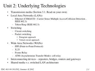
Transmission media (Section 3.1. Read on your own) Local Area Networks (LANs) Ethernet (CSMA/CD - Carrier Sense Multiple Access/Collision Detection , IEEE 802.3) Token Ring (IEEE 802.5) Switching Circuit switching Packet switching Datagram approach Virtual circuit approach

Unit 2: Underlying Technologies
E N D
Presentation Transcript
Transmission media (Section 3.1. Read on your own) Local Area Networks (LANs) Ethernet (CSMA/CD - Carrier Sense Multiple Access/Collision Detection , IEEE 802.3) Token Ring (IEEE 802.5) Switching Circuit switching Packet switching Datagram approach Virtual circuit approach Wide Area Networks (WANs) PPP (Point-to-Point Protocol) X.25 Frame Relay ATM (Asynchronous Transfer Mode)- cell relay Interconnecting devices – repeaters, bridges, routers and gateways Shared media v.s. switched LAN architecture Unit 2: Underlying Technologies
Ethernet LANs Features 1) Widest Industry Use and Acceptance a) Product Availability b) Many Vendors c) Low Cost d) High Knowledge Base 2) Standardized for Multiple Media Types a) Twisted Pair (10Base-T) b) Optical Fiber (10Base-F, FOIRL) c) Coaxial Cable (10Base2, 10Base5) d) Also high-speed Ethernets
Ethernet Problems 1) Coaxial Cable Networks Hard to Troubleshoot a) Faulty connections and electrical failures hard to find b) Improper grounding can cause stray voltages c) Static electricity d) Non-standard hardware e) Problems are often intermittent 2) Ethernet Lacks Built-In Network Monitoring 3) Ethernet Lacks Any Priority Mechanism 4) Station Transmission Time May Grow Large under High Loads
Carrier Sense Multiple Access with Collision Detection (CSMA/CD) The basic idea: When a station has a frame to transmit: 1) Listen for Data Transmission on Cable (Carrier Sense) 2) When Medium is Quiet (no other station transmitting): a) Transmit Frame, Listening for Collision b) If collision is heard, stop transmitting, wait random time, and transmit again. Frame format This portion must be at least 64 bytes for the Ethernet to work correctly
Token Ring Features 1) Predictable Performance a) Unlike Ethernet, there is a fixed limit on how long a station must wait to transmit frame. b) Eight data priority levels ensure that important data get sent first. 2) Ring-of -Stars Topology a) Star layout is well understood. b) Ring is easily expanded by adding additional Multistation Access Units (MAUs) c) Only point-to-point data connections used. 3) Self-Monitoring and Reconfiguration Capabilities a) Active Monitor station recovers from any token operation problems. b) If any station goes down it will be detected and removed from the ring. c) Any single cable can be cut or disconnected and network will reconfigure and continue operation.
Token Ring Features (continued.) 4) IBM Support a) IBM SNA data and LAN data can travel together on same token ring. b) Token Ring is an integral part of IBM future networking. Disadvantages of Token Ring 1) Higher price for NICs 2) Limited support for non-IBM products. a) Fewer products available for Token Ring than Ethernet b) Ethernet is still at the heart of some vendors’ future network plans. Note: For this course, you do not need to know the details of Token Ring frame format
Figure 3-19 Circuit Switching • Dedicated physical connections • Source and destination operate at the same speed • Data arrive in sequence
Packet Switching • Store-and-forward • Source and destination may operate at different rates Figure 3-20 Packet Switching- Datagram approach
Packet Switching- Datagram approach • Connectionless • No connection setup necessary before sending data • Each packet sent independently • Each packet may take different path to destination • Each packet contains complete destination address • Packets may arrive out-of-order (transport layer must do reordering) • Network load is completely unpredictable • Protocol Examples: IP, Novell IPX, AppleTalk
Packet switching – Virtual circuit approach • Connection-oriented • Sender sends a Setup Request packet to establish a virtual circuit before sending data • Setup Request passes through all router/switches on path from source to destination • Path is assigned a Virtual Circuit Identifier (VCID) • Each router/switch stores information about each VC • Any router/switch or destination may deny the setup request (like a busy signal). • When finished, Sender sends Clear Request to tear down VC. • Each data packet contains VCID, not full source and destination addresses • All packets follow same path and arrive in order • Network load can be controlled through admissions control (denying setup requests if busy) • Protocol Examples: X.25, Frame Relay, ATM
WAN • PPP • commonly used for dial-up access to the internet (connect through a phone line to the access router) • can also be used in a point-to-point link between two devices such as routers Figure 3-22 Point-to-point protocol (PPP) frame
Figure 3-23 X.25 (Connection-oriented) X.25 - An interface protocol to access the network Not defined by X.25
Figure 3-25 Hop-by-hop error and flow control in X.25 is not necessary for newer more reliable networks.
Transparent Bridge DA: Destination Address SA: Source Address