Download
1 / 34
340 likes | 522 Vues
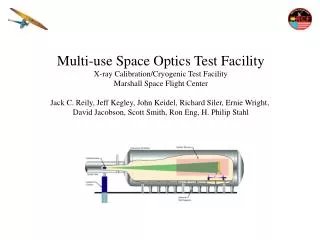
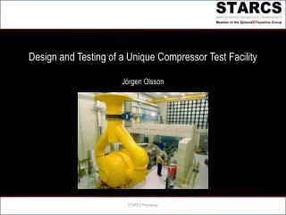
Design and Testing of a Unique Compressor Test Facility Jörgen Olsson. Outline of the presentation. Introduction Specifications Design Hardware Test Compressors Testing Summary. What type of compressors are tested?. Low Pressure Compressor. RM 12 (GE F404). Why are compressors tested?.

E N D
Design and Testing of a Unique Compressor Test FacilityJörgen Olsson STARCS Proprietary
Outline of the presentation • Introduction • Specifications • Design • Hardware • Test Compressors • Testing • Summary STARCS Proprietary
What type of compressors are tested? Low Pressure Compressor RM 12 (GE F404) STARCS Proprietary
Why are compressors tested? • Measure the performance of a new design • Map the operational envelope • Establish the operational limits to avoid stall, surge and flutter • Verification of design models STARCS Proprietary
Main design criteria for the Compressor Research Facility • Drive power 4.3 MW • Rotation speed ranges: 0-5500 rpm and 0-25000 rpm, continuously variable • Variable inlet pressure • Variable outlet pressure • Air flow through the test facility without a test compressor installed • Efficient sound proofing of the control room and to the external environment. • Control system with safety monitoring and logging STARCS Proprietary
Envelope of the Compressor Test Facility STARCS Proprietary
STAL-LAVAL (Siemens Turbomachinery Finspång Sweden)Compressor Test Facility In service fall 1973 6 MW STARCS Proprietary
First sketch STARCS Proprietary
Compressor Test Facility Overview STARCS Proprietary
Side view of the Compressor Test Facility Asynchronous motor 4.3 MW Inlet valve Test object (rig) Outlet valve (2) Counter weight Control valve for ejector primary flow STARCS Proprietary
The Compressor Test Facility seen from the motor Inlet valve Outlet valve Outlet valve To acoustic baffles and exhaust tower Floor level Control valve for ejector primary flow Ejector STARCS Proprietary
Inlet flow manipulators Perforated plate Net Net Net STARCS Proprietary
Modified ejector Insert STARCS Proprietary
Gearboxes Sketch of the gear box for 25000 rpm Cut away sketch of the gearbox for 5500 rpm STARCS Proprietary
Torque meters 0-10 kNm 0-8000 rpm 0-1400 Nm 0-30000 rpm STARCS Proprietary
Situation plan STARCS Proprietary
External view of the building STARCS Proprietary
Motor and 25000 rpm gear box STARCS Proprietary
Gear box and exhaust annular collector STARCS Proprietary
Air inlet with inlet valve and stagnation chamber STARCS Proprietary
Hardware needed to adapt a test compressor STARCS Proprietary
Inlet pipe STARCS Proprietary
Diffuser STARCS Proprietary
Vital booster and instrumentation rack STARCS Proprietary
Overview of the control and measurement system Zephyr Recording of fast response data Bandwidth: 30 kHz On-line monitoring Data to customer Strain gauges FFA 1260 Signal conditioning Instationary Pressures FFA 1220 Signal conditioning Alarm System Compilation of data and presentation online of data, RMS, FFT etc. Alarm can invoke emergency stop IDA Recording of data Bandwidth:10 Hz On-line monitoring. Facility fixed transducers Temperatures Electronic Pressure Scanners (ESP) Recording of ”slow” pressures. (10 Hz) On-line monitoring. MAESTRO Test sequence control Bearing temperature and vibration Stationary Pressures ABB 800 Control system for motor and valves On-line monitoring. Emergency stop Motor control sensors STARCS Proprietary
Control Room STARCS Proprietary
Control System Display STARCS Proprietary
On-Line Compressor Performance Map STARCS Proprietary
Hulda low pressure compressor STARCS Proprietary
Vital LPC STARCS Proprietary
AIDA Aggressive Duct With Hulda Compressor STARCS Proprietary
Test compressor for max 5500 rpm Front view of Siemens Industrial Turbo-machinery test compressor with first stage guide vanes. (inlet hub not present) STARCS Proprietary
What is measured? • Inlet and outlet pressures and temperatures • Mass flow, rotational speed and drive shaft torque • Vibration and loads on the rotor blades using strain gauges or tip-timing • Vibration and loads on the stator vanes and the inlet guide vanes using strain gauges • Stall detection using temperature sensors and unsteady pressure transducers • Static pressures in the flow channel • For monitoring: Rotor tip clearance, shaft position, temperature and vibration of the compressor bearings, lubrication oil pressure, temperature and mass flow • Flow properties in the channel using traversing probes: pressure, temperature and flow angles
Summary • STARCS in-house designed and built Compressor Test Research Facility • Today a well proven concept • Drive power and mass flow capabilities in parity with customer demands • Unique capabilities with sub atmospheric outlet STARCS Proprietary