Download
1 / 23
230 likes | 318 Vues
Learn about the operation and monitoring of the CMS Regional Calorimeter Trigger system, key components, latency, algorithms, and dataflow. Understand the functionality of the Level-1 Trigger system in managing high-PT physics data at LHC beam crossings.

E N D
Operation and Monitoring of the CMS Regional Calorimeter Trigger • P. Klabbers, S. Dasu, J. Efron, T. Gorski, K. Grogg, • M. Grothe, M. Jaworski, J. Lackey, C. Lazaridis, • J. Leonard, P. Robl, A. Savin, W.H. Smith, M. WeinbergPhysics Department, University of Wisconsin,Madison, WI, USA • TWEPP 2008 • September 2008 • The pdf file of this talk is available at: • http://indico.cern.ch/contributionDisplay.py?contribId=116&sessionId=9&confId=21985 • See also the CMS Level 1 Trigger Home page at • http://cmsdoc.cern.ch/ftp/afscms/TRIDAS/html/level1.html
CMS Trigger & DAQ Systems • Level-1 Trigger • LHC beam crossing rate is 40 MHz & at full Luminosity of 1034 cm-2s-1109 collisions/s • Reduce to 100 kHz output to High Level Trigger and keep high-PT physics • Pipelined at 40 MHz for dead time free operation • Latency of only 3.2 msec for collection, decision, propagation Level-1 Detector Front-ends Trigger Readout Event Controls Switch Fabric Manager Farms Computing Services
The CMS Level-1 Trigger &Regional Calorimeter Trigger • Only calorimeter and muon systems participate in CMS L1 3<||<5 ||<3 ||<3 ||<2.1 0.9<||<2.4 ||<1.2 4K 1.2 Gbaud serial links Cu cables e/, jets, ET, HT, jet counts muons • Regional Calorimeter Trigger • Receives Trigger Primitives (TPs) from 8000 ECAL/HCAL/HF towers • Finds 28 e/g candidates, creates 14 central tower sums, 28 quality bits, and forwards 8 HF towers and 8 HF quality bits • All sent to Global Calorimeter Trigger at 80 MHz on SCSI cables
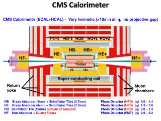
CMS Calorimeter Geometry EB, EE, HB, HE map to 18 RCT crates Provide e/g and jet, t, ET triggers
Calorimeter-RCT Mapping • 18 crates handle the entire CMS calorimeter seamlessly • Each crate covers a 0.7 f by 5 h region • Each Receiver - Electron ID Card pair covers a 0.35 f by 0.7 h region (ex. one 0.7 f by 0.5 h) • Single Jet/Summary card receives HF, finds 8 e/g, sets Quiet bits and forwards Sums, e/g, and all bits to GCT
Calorimeter Trig. Algorithms • e/g Rank = Hit+Max Adjacent Tower • Hit: H/E < Small Fraction • Hit: 2 of 5-crystal strips >90% ET in 5x5 Tower (Fine Grain) • Isolated e/g (3x3 Tower) • Quiet neighbors: all 8 towerspass Fine Grain & H/E • One of 4 corners 5 EM ET < Thr. • Jet or t ET • 12x12 trig. tower ET sliding in 4x4 steps w/central 4x4 ET > others • t: isolated narrow energy deposits • Energy spread outside t veto pattern sets veto • t Jetif all 9 4x4 region t vetoes off
RCT Crates Master Clock Crate (MCC) Main RCT Crate • One crate with 3 custom cards to create and fan-out 160 & 120 MHz clocks, ReSync, and Bunch Crossing Zero to 18 RCT Crates’ Clock & Control Cards • Clock Input Card (CIC) - 1/5* • Source: LHC clock or on-board Oscillator • Fine and course delay up to 25 ns • Clock Fanout Card to Crates (CFCc) & Clock Fanout Card Midlevel (CFCm) – 2/7* & 7/13* resp. • Fine delay adjust to all crates • Signals distributed on 36 4-pair low-skew cables of the same length. VME 48V DC Power 160 MHz Diff. ECL 0.4 Tbit Point-to-point Dataflow Designed by J. Lackey 18/26* crates with custom backplane incorporate algos: e/g, t & Jet Triggers *used/total produced
RCT Cards Clock & Control 18/25* - 1 per crate Receiver 126/158* - 7 per crate • Provides 160 MHz & 120 MHz clocks, reset, BC0 to one RCT crate, phase and delay adjustable. • Clock from Master Clock Crate fed by CMS Trigger Timing and Control (TTC) System Receives 128 E & HCAL towers on 1.2 GB Cu Links (Vitesse 7216-1) on RMC’s Phase, Adder, and Boundary Scan ASICs to realign/deskew data in, regional sums, sync 50 towers for e/g algo Memory LUT at 160 MHz Electron ID 126/157* - 7 per crate Jet Summary 18/25* - 1 per crate • e - g - m • Sort ASICs receive data on BP & find top iso. & non-iso.) • 14 Quiet Bits by threshold on JS • 14 MinIon bits from RC • Forward Calorimeter (HF) RMC & LUTs for HF ET’s • Regional (4x4 tower) sums to GCT • Sort (disabled) ASIC for BP receive and EISO ASIC fully implements e/g algorithm • Sends highest ET iso and non-iso e/g for 2 4x4 regions sent to JSC • 28 e/g candidates per crate via BP to JSC • 7x2 Iso & 7x2 Non-Iso *used/total produced
ECAL and HCAL Input to RCT • Both HCAL HTR (HCAL Trigger and Readout) and ECAL TCC (Trigger Concentrator Card) use a Serial Link Board (SLB) with the Vitesse V2716-1 link chip on it • Configurable mezzanine card • Two Altera Cyclone FPGAs synchronize data for V2716 and calculate Hamming Code • Clocking separate • Ensures data in time between subsystems • HTR • Up to six SLBs send Trigger Primitives (TPs) • TCC • Six or nine SLBs send Ps • Both TCC & HTR Receive front-end data on fibers • Initial tests as early as 2004 • Installed and in use on all TP boards HTR SLBs TCC
RCT Output to GCT • Each RCT crate is connected to 3.5 GCT Source Cards (SCs) • RCT output differential ECL • On 6 SCSI cables per crate • 63 SCs needed • 2 RCT-GCT cable inputs/SC • 45 for Regional Sums • Duplication needed on =0 for jet algo - one input used • 9 with inputs from 2 different crates • 18 for iso-e/ and noniso-e/ candidates, muon bits • SC sends data on fibers to main GCT crate • GCT turns regional sums to jet candidates, sorts jet and e/ candidates, computes missing ET, HT, jet counts and sends to Global Trigger (GT) Source Card Crate RCT Crate Front
RCT Hardware Installation and Commissioning at CMS • One RCT Master Clock and 18 RCT crates tested and cards installed • All cabling installed: input HCAL, HF, ECAL, RCT internal data sharing, and output to GCT • Input cabling complete • Total: 1026 SLB-RCT Crate Rear Front of Racks Rear of Racks 56 ECAL/HCAL input cables per crate (Beige) 11 Data sharing connections per crate (Black) Full system = 19 Crates 18 HF input 108 Cables to GCT
Operations: Detector Slow Control and Rack Monitoring System Rack 1 Control Panel • One Custom-built Rack Monitor Card installed in July 2006 per rack: • Monitors power supplies, temperatures, fans • Configurable - alarm set points, number of fans, power supplies connected… • Ability to turn on and off system, check for and acknowledge alarms, send notification of… • Connects to network via a COMTROL serial-to-ethernet port • Slow Control software was developed using PVSS (Prozessvisualisierungs und Steuerungs-System) • Fully Implemented in USC55 • Exploits all above functionality • Keeps values in database • Histograms available • Fully integrated into CMS DCS Rack 1 Crate A Temperatures Rack Monitor Card and power chassis Power & Temp. Fans & Monitoring
Operations: RCT Trigger Supervisor • CMS Trigger Supervisor • An online software framework to configure, test, operate, and monitor the trigger components and manage communications between (sub)systems • Set up as individual subsystem cells and a central cell directing multiple systems at once with SOAP commands • RCT Trigger Supervisor handles • System configuration via a pre-defined key for data taking, internal tests, and multi-system interconnection tests • Central configuration of trigger systems by CMS Run Control for data taking and interconnection tests • User configuration • Accesses databases for configuration including channel masking • Provides interface for creating new keys RCT Configuration
Operations: RCT Trigger Supervisor RCT Monitoring • RCT Trigger Supervisor also handles Crate monitoring • RCT hardware registers and errors • Can mask channels not in use in monitoring panel • Using a file or DB • Will log monitored values in DB • Link errors, etc. • Alert and alarm functionality • RCT expert now • Development of more central alarm system for TS underway
Operations: RCT Intercrate Testing • Uses the ability of the RCT to cycle the addresses of its input LUTs on the Receiver cards (emulate up to 64 crossings) • All 18 RCT crates used and GCT Source Cards capture output • Pattern into emulator to predict output and compare with capture • GCT Source Cards are very flexible - multiple capture options including BC0, output patterns, and ReSync • First tests were internal, testing timing between RCT crates • Check sharing on every edge, for every tower, timing tolerances • Walking zeros & ones, random, ttbar simulated data like • ttbar: Partial output at right • Problems found and fixed • Checked RCT-GCT connections • Integrate into Trigger Supervisor • Developing tests using patterns injected at TPG level • Tests SLB-RCT link, algos.
Analysis: RCT Trigger Emulator • Software with the goal of exactly reproducing the L1 Trigger hardware response, including: • Use and generate Look-Up Tables (LUTs) • Include Hardware and Firmware registers and any other configuration options • Access same database as TS to get configuration information • It is to be used for hardware validation and monitoring • In use by the calorimeter trigger to predict the response of the full chain to patterns injected at the trigger primitive level • Online and offline Data Quality • 18-Crate test • Link tests (patterns injected at TP level) • In this way the hardware and the emulator are fully vetted • Bugs are tracked down and fixed in firmware, hardware and software • In reverse: simulation can be used to inject physics patterns into the hardware • Validation of algorithms
Global Runs and Data Taking • In order to integrate detectors and get ready for first beam • Use cosmic rays and study noise rates • 2 days to 1 week periods • Designated periods since Fall 2007 • Various subsystems participate • RCT took part in most runs with HCAL and/or ECAL providing TPGs • GCT e/g path was commissioned first • RCT LUTs very flexible – forward HCAL or ECAL to e/g path for triggering • Each different scenario required different LUT configuration • Created an individual Trigger Supervisor Key to describe each one • Study data offline to validate algorithms and detect any problems • Use Data Quality Monitoring – Online and Offline • First circulating beam arrived 10.9.2008! • Have had additional beam since then, expect first collisions soon…
RCT Data Quality Monitoring • Online: real time histograms created and filled in the High-Level-Trigger Filter farm during data taking • Also can go back in time to a recent run • Compare withreference histograms • Highlighted if in error • Real time data validity checkswith emulator • Data delivered ata rate of ~1-10 Hz • Selected histogramsfor shift crews ECAL Barrel to e/g (each block is an RCT Region)
RCT Data Quality Monitoring • Offline – more detailed analysis possible • Access to a greater number of events than online • Book more histograms and store an nTuple • Can be run on CMS online machines for near real-time analysis • Feed emulator TPGs and get efficiencies, inefficiencies, and overefficiencies • Valuable debugging tool fbin hbin HCAL Barrel & Endcap to e/g fbin hbin Rank h = 0
RCT Data Quality Monitoring • Offline – more detailed analysis • Very valuable during early runs with special conditions • Can retrieve a single tower or region • Energy difference to see problems at the bit level • Compare in 1D to see subtle differences • Use emulator to find extra and missing candidates (overefficiency an inefficiency) Cable loose – stuck bit Another stuck bit – some debugging to do Some of calorimeter masked
Recently CMS Closed 6 Sep 2008 First beam 10 Sep 2008 at ~9:30! Calorimeters in pink & blue HF in foreground
Finally • CMS Regional Calorimeter Trigger boards produced and installed • Successful commissioning and integration • 19 crates and all boards installed • Tools necessary for operation in place • RCT DCS integrated with central CMS DCS • Alerts/alarms go to central control as well as to RCT personnel • RCT Trigger Supervisor to configure, monitor, and test the RCT • Integrated with Central Trigger Supervisor, controlled by CMS Run Control during daily data taking • Starting real data taking • RCT DQM and emulator • Online and offline analysis to study RCT • Found problems early using cosmic ray and noise runs • RCT flexible • GCT had e/g trigger ready first • RCT could send either HCAL or ECAL TPGs down e/g path • Trigger Supervisor Keys set up for a large range of scenarios as we commissioned • Calorimeter trigger on for first beam. • RCT is ready and anxious for colliding beams!