Download
1 / 1
10 likes | 251 Vues
GPS Guided Autonomous Vehicle Navigational System. Straight Path Navigation

E N D
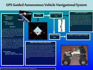
GPS Guided Autonomous Vehicle Navigational System Straight Path Navigation Because of the innate inaccuracy of GPS, the vehicle cannot move from a start point to end point in a perfectly straight line. Each subsequent GPS reading has the potential of varying from the previous reading by up to 3 meters. To remedy this problem, the system waits till the machine is moving at operating speed. At this speed, the heading angle with respect to north is computed and is compared to the angle of the intended path with respect to north. Based on slight deviations (shown in brown), the vehicle turns left or right. Maintain Straight Line Startup Authors: Navik Agrawal Greg Kuperman Bashar Saleh Advisors: Mr. Phil Farnum Mr. Sid Deliwala ABSTRACT The lawnmower is a vehicle that naturally lends itself for a GPS application. One can assume, quite realistically, that a lawnmower will operate outdoors in a large open field. Such an area is an ideal location for GPS to function at its best. The question remains whether or not the accuracy of GPS, which is up to three meters 95% of the time, would allow GPS to successfully navigate a lawnmower. Results indicate that the non error corrected GPS measurements will be able to navigate an RC vehicle with a decent degree of accuracy. The average deviation from the path is approximately one meter. The navigational system is implemented on an RC vehicle (TXT-1) obtained form the GRASP Laboratory from the University of Pennsylvania. Eventually, the navigational system will be adapted to a full scale lawnmower in a future senior design project. Demonstration: April 21st, Thursday 9:00 am, 1:00 pm, 1:30 pm, 2:00 pm End Point Perpendicular Boundary Lines Boundaries Deviation from Path Start point Vehicle Trajectory Complete Traversing Entire Region Continue along Path Initial Path-findingAlgorithm With this algorithm, the vehicle can be placed in any direction within the boundaries. With the four corners of the region, four perpendicular boundary lines (shown in teal) are created. Once the car accelerates to operating speed, the system obtains the heading of the vehicle with respect to north and the GPS coordinates. With these two values, the vehicle’s projected trajectory (shown in brown) can be computed. Then, the system computes the intersections of the projected trajectory and perpendicular boundary lines (shown in red). From these intersections, the system determines which intersection points are in the direction of movement and which point is closest. Once the vehicle arrives at the closest intersection point, the vehicle will turn onto the path. Thus, the system can put the vehicle onto the correct path regardless of the starting conditions. University of Pennsylvania, Department of Electrical and Systems Engineering