Download
1 / 13
130 likes | 230 Vues
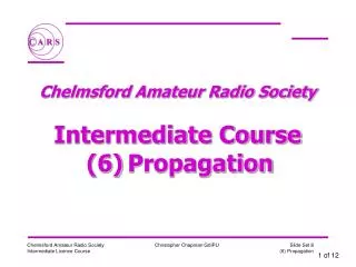
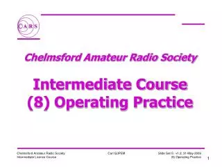
Chelmsford Amateur Radio Society Intermediate Course (5) Antennas and Feeders. Standing Wave Ratio Meter. Antenna. Feeder. System. 50 Ohms Output. Antenna Matching Unit. Transmitter. Receiver. . Feeders. Feeder types: Coaxial, Twin Conductors.

E N D
Chelmsford Amateur Radio Society Intermediate Course(5) Antennas and Feeders
Standing Wave Ratio Meter Antenna Feeder System 50 Ohms Output Antenna Matching Unit Transmitter Receiver
Feeders • Feeder types: Coaxial, Twin Conductors Inner Conductor is shrouded by dielectric, with outer (braided) screen. For Radio 50 Coax is used (TV is 75) Two conductors kept at constant separation by insulation - no screen Balanced Feeder is available in 75-300
A B B A Feeder Impedance • Feeder Impedance is a form of AC Resistance • Impedance is based on the Ratio of A and B
Balanced/Unbalanced • Coax is unbalanced - Inner has signal, Outer is at ground. • Twin feeder is balanced - conductors have equal and opposite voltages/currents/fields. • Mounting Twin Feeder near to conducting objects will cause an imbalance in the conductors and unwanted radiation
Decibels • Gains and Losses are expressed in dB’s • 3 dB is half steps and 6dB is quarter steps • You will need to remember this table for exam: 3dB x2 or a half 6dB x4 or a quarter 9dB x8 or an eighth 10dB x10 or a tenth
Feeder Losses • ALL feeders have loss, the longer the feeder the greater the loss. Twin feeder has a lower loss than Coaxial cable • This loss is both in Transmit and Receive modes. • For some standard cables the loss is: Per 100mRG58RG213 10 MHz 4.8 dB 2.0 dB 30 MHz 8.2 dB 3.2 dB 144 MHz 21 dB 8.6 dB
Antenna’s • All Antennas have a feed point impedance. • This is determined by the dimensions which will relate to the wavelength of the applied signal and the height of antenna. • Dipoles are a half wave length long and are a resistive match at only one frequency. • If you replace the antenna by a resistor of the same value as the feed point impedance the transmitter will not be able to tell the difference. • Dipoles in theory are 73 ohms but in practice approx 65 ohms so close enough to the course value of 50 ohms.
I V 2 0 1/4 WAVELENGTH 1/4 WAVELENGTH 1/4 WAVELENGTH 1/4 WAVELENGTH Voltage Standing Wave Ratio • If the feed point impedance is incorrect then it will not match the impedance of the feeder and some energy will be reflected back down the feeder. • When this reflected energy is returned to the Transmitter it is again reflected back to the antenna and is radiated. • The combined energy is known as the forward and reflected power and gives rise to the Standing Waves on the feeder.
x Electric Field, E y Direction of Propagation z Magnetic Field, H Electromagnetic Waves • Electromagnetic radiation comprises both an Electric and a Magnetic Field. • The two fields are at right-angles to each other and the direction of propagation is at right-angles to both fields. • The Plane of the Electric Field defines the Polarisation of the wave.
Polarisation • Polarisation is the plane of the antennas radiating electric field. • Common polarisations are Horizontal and Vertical. • Transmitter and receiving antenna polarisation need to match for optimum signal strength, especially at VHF/UHF • Verticals (/4, 5/8) give vertical polarisation. • Yagi and Dipoles antenna’s may be either horizontal or vertical depending on their mounting.
Dipole Radiation Pattern Radiation Pattern for a Vertical Dipole:-
Direction of Radiation Unwanted Sidelobes Yagis Boom Radiation Pattern Feeder Directors Driven Element Reflector