
Uploaded by
zorion
1 SLIDES
153 VUES
10LIKES
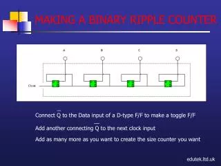
MAKING A BINARY RIPPLE COUNTER
DESCRIPTION
This tutorial demonstrates how to connect the Q output of a D-type flip-flop to create a toggle flip-flop. By adding additional Q outputs to successive clock inputs, you can easily build a binary ripple counter of any size. The step-by-step guide will help you understand the functioning of each flip-flop in the ripple counter configuration, making it ideal for both beginners and those looking to enhance their digital electronics skills.
Download
1 / 1
Télécharger la présentation 
MAKING A BINARY RIPPLE COUNTER
An Image/Link below is provided (as is) to download presentation
Download Policy: Content on the Website is provided to you AS IS for your information and personal use and may not be sold / licensed / shared on other websites without getting consent from its author.
Content is provided to you AS IS for your information and personal use only.
Download presentation by click this link.
While downloading, if for some reason you are not able to download a presentation, the publisher may have deleted the file from their server.
During download, if you can't get a presentation, the file might be deleted by the publisher.
E N D
Presentation Transcript
Connect Q to the Data input of a D-type F/F to make a toggle F/F Add another connecting Q to the next clock input Add as many more as you want to create the size counter you want MAKING A BINARY RIPPLE COUNTER edutek.ltd.uk


More Related