Download
1 / 24
240 likes | 359 Vues
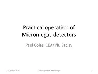
Practical operation of Micromegas detectors. Paul Colas, CEA/ Irfu Saclay. Content. Micromegas principle of operation Different kinds of Micromegas Various meshes On-frame Pillars on PCB Pillars on mesh Bulk InGrid Microbulk « Cooking » process Examples. S1. S2.

E N D
Practical operation of Micromegas detectors Paul Colas, CEA/Irfu Saclay Practical operation of Micromegas
Content • Micromegasprinciple of operation • Differentkinds of Micromegas • Variousmeshes • On-frame • Pillars on PCB • Pillars on mesh • Bulk • InGrid • Microbulk • « Cooking » process • Examples Practical operation of Micromegas
S1 S2 Micromegas: How does it work? Y. Giomataris, Ph. Rebourgeard, JP Robert and G. Charpak, NIM A 376 (1996) 29 MicromeshGaseousChamber: a micromeshsupported by 50-100 mm insulatingpillars, and heldatVanode – 400 V Multiplication (up to 105 or more) takes place between the anode and the mesh and the charge iscollected on the anode (one stage) Funnelfieldlines: electrontransparencyvery close to 1 for thinmeshes Small gap: fast collection of ions S2/S1 = Edrift/Eamplif ~ 200/60000= 1/300 Practical operation of Micromegas
A GARFIELD simulation of a Micromegas avalanche (Lanzhou university) Small size => Fast signals => Short recovery time => High rate capabilities micromesh signal strip signals Electron and ion signals seen by a fast (current) amplifier In a TPC, the signals are usually integrated and shaped Practical operation of Micromegas
Gain Gain of Ar mixtures measured with Micromegas (D.Attié, PC, M.Was) Practical operation of Micromegas
MESHES Many different technologies have been developped for making meshes (Back-buymers, CERN, 3M-Purdue, Gantois, Twente…) Exist in many metals: nickel, copper, stainless steel, Al,… also gold, titanium, nanocristalline copper are possible. Chemically etched Deposited by vaporization Electroformed Wowen Laser etching, Plasma etching… PILLARS 200 mm Can be on the mesh (chemical etching) or on the anode (PCB technique with a photoimageable coverlay). Diameter 40 to 400 microns. Also fishing lines were used (Saclay, Lanzhou) Practical operation of Micromegas
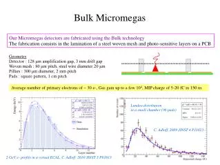
The Bulk technology Fruit of a CERN-Saclay collaboration (2004) Mesh fixed by the pillars themselves : No frame needed : fully efficient surface Very robust : closed for > 20 µ dust Possibility to fragment the mesh (e.g. in bands) … and to repair it Used by the T2K TPC under construction Practical operation of Micromegas
The Bulk technology Practical operation of Micromegas
‘Choose your material For first tests of a detector, a power supply with current limitation is preferred. Set the current limitation at 500 nA for instance. The CAEN N471A is ideal for testing, though not very precise. They have 2 chanels, you can use one for the mesh and one for the drift cathode. Check your gasbox for gas-tightness : must bubble down to 1 l/h. Before connecting the electronics, ‘cook’ your detector (see next slide). Preamp: use a protected fast preamp (for instance ORTEC 142 series) and an amplifier-shaper (0.5 or 1 microsecond peaking time), for instance ORTEC 472 or 672. Hunt noise (microphonic noise, radiated noise, noise from the grounds) Practical operation of Micromegas
‘Burning’ or ‘cooking’ your detector To make the detector stable for further operation, it must be ‘cooked’ : raise the voltage slowly to 550-600 V (50 micron gap) or 800-900 V (128 micron gap), step by step, to the level where it starts sparking. This has to be done in air It consists of burning small dusts (mostly fibres). A relatively high (ionic) current (200-250 nA) can remain. It will decrease after circulation of the gas and go down to 0(1nA). A detector which stands its voltage in air will always work in gas. Practical operation of Micromegas
KEK Japan 2007 - Detector used • Multi-purpose gas box (D. Attié, P.C., A. Giganon, M. Riallot) designed in Saclay. • 2 copies in Saclay for Medipix/Timepix and Ingrid measurement, 1 built in Japan for energy resolution measurements (plus in the future) • Gas : Ar+ few % isobutane P. Colas, Measurement of energy resolution
Chromium K-edge (Center for X-Ray Optics) P. Colas, Measurement of energy resolution
Cr foil source Drift cathode mesh P. Colas, Measurement of energy resolution
Result : 5.6% r.m.s. resolution (Broken record) Noise very small thanks to adequate filter on the mesh P. Colas, Measurement of energy resolution
Aachen • 9-11 octobre 2006. Démonstration d’un Micromégas. • 24-25 octobre 2006. remove 10 MOhm resistors on HV, then shield • Resolution 6.7%rms.
Loussaïf Abdelkader Asma Barbouchi Borhan PC Nidhal Kahlaoui Wacel Hamani Mohamed Ali Nasri Abdelli Wahid Nidhal Kahlaoui