Chapter 25: Electric Circuits
Chapter 25: Electric Circuits. Resistors in series. V. V. Resistors in Series and Parallel. Resistors in parallel. V. V. Resistors in Series and Parallel. Example 1:. Resistors in Series and Parallel. Example: (cont’d). I 4. I 2. R 2. R 4. I 3. Resistors in Series and Parallel. I.

Chapter 25: Electric Circuits
E N D
Presentation Transcript
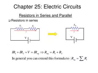
Chapter 25: Electric Circuits • Resistors in series V V Resistors in Series and Parallel
Resistors in parallel V V Resistors in Series and Parallel
Example 1: Resistors in Series and Parallel
Example: (cont’d) I4 I2 R2 R4 I3 Resistors in Series and Parallel I R3 DV
Example: (cont’d) Resistors in Series and Parallel
Loop 2 i i i2 i1 Loop 1 i i i2 • Introduction • Many practical resistor networks cannot be reduced to simple series-parallel • combinations (see an example below). • Terminology: • A junction in a circuit is a point where three or more conductors meet. • A loop is any closed conducting path. junction Kirchhoff’s Rules junction
Kirchhoff’s junction rule • The algebraic sum of the currents into any junction is zero: Kirchhoff’s Rules
Kirchhoff’s loop rule • The algebraic sum of the potential differences in any loop, including • those associated with emfs and those of resistive elements, must equal • zero. Kirchhoff’s Rules
Rules for Kirchhoff’s loop rule Kirchhoff’s Rules
Rules for Kirchhoff’s loop rule (cont’d) Kirchhoff’s Rules
Solving problems using Kirchhoff’s rules Kirchhoff’s Rules
Example 1 Kirchhoff’s Rules
Example 1 (cont’d) Kirchhoff’s Rules
Example 1 (cont’d) Kirchhoff’s Rules
Loop 2 i i i2 i1 Loop 1 i i i2 Find all the currents including directions. • Example 2 Kirchhoff’s Rules Loop 1 Loop 2 multiply by 2 i = i1+ i2
Galvanometer To be discussed in a later class. Electrical Measuring Instruments
Ammeter Electrical Measuring Instruments
Ammeter (cont’d) Electrical Measuring Instruments
Voltmeter Electrical Measuring Instruments
Charging a capacitor R-C Circuits
Charging a capacitor (cont’d) R-C Circuits
Charging a capacitor (cont’d) R-C Circuits
Charging a capacitor (cont’d) R-C Circuits
Charging a capacitor (cont’d) R-C Circuits
Discharging a capacitor R-C Circuits
Discharging a capacitor (cont’d) R-C Circuits
Discharging a capacitor (cont’d) R-C Circuits
Problem 1 Rc=25.0 W • The resistance of a galvanometer coil is 25.0 W, • and the current required for full-scale deflection • is 500 mA. • Show in a diagram how to convert the galvano- • meter to an ammeter reading 20.0 mA full scale, • and compute the shunt resistance. • b) Show how to convert the galvanometer to a • voltmeter reading 500 mV full scale, and compute • the series resistance. 500 mA 20 mA Rs a) ammeter Exercises Rc=25.0 W Solution a) For a 20-mA ammeter, the two resistance are in parallel: Vc=Vs->IcRc=IsRs->(500 x 10-6 A)(25.0 W) = (20 x 10-3 A – 500 x 10-6 A)Rs-> Rs=0.641 W. b) For a 500-mV voltmeter, the resistances are in series: Vab=I(Rc+Rs)->Rs=Vab/I – Rc -> Rs=500 x 10-3 V / 500 x 10-6 A – 25.0 W = 975 W. 500 mA Rs a b Vab=500 mV b) voltmeter
Problem 2 5.00 W 20.0 V + I1 I2 + v 36.0 V 2.00 W 4.00 W v v v + I1-I2 14.0 V Exercises
Problem 3 • What is the potential of point a with respect • to point b when the switch S is open? • Which point, a or b, is at higher potential? • Now the switch S is closed. • What is the final potential of point b? • How much charge flows through switch S • when it is closed? V=18.0 V 6.00 W 6.00 mF Solution b a S • With an open switch: • Also, there is a current in the left branch: • So • Point b is at the higher potential. • If the switch is closed: • New charges are: 3.00 mF Exercises 3.00 W The total charge flowing through the switch is 5.40 x 10⁻⁵ C.