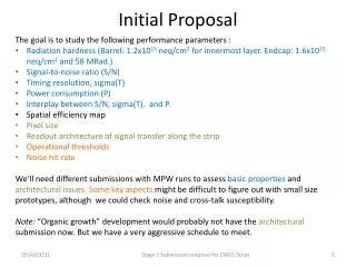
Initial Proposal for TGaf PHY
Initial Proposal for TGaf PHY . Authors:. Date: 2011-11-08. Slide 1. Outline. Propose initial PHY details for TGaf based on TGac with possible enhancements based on TGah. . Slide 2. Overview . It was decided to base TGaf PHY on TGac during the May meeting [1]

Initial Proposal for TGaf PHY
E N D
Presentation Transcript
Initial Proposal for TGaf PHY Authors: Date:2011-11-08 Ron Porat, Broadcom Slide 1
Outline • Propose initial PHY details for TGaf based on TGac with possible enhancements based on TGah. Ron Porat, Broadcom Slide 2
Overview • It was decided to base TGaf PHY on TGac during the May meeting [1] • TGac provides many useful features to TGaf such as • Support for 4 different BW options (20/40/80/160MHz) • Support for non-contiguous transmission (80+80) – important for cases where spectrum availability is fragmented such as in large metropolitan areas • DL MU-MIMO – important for increasing network throughput especially if MIMO spatial multiplexing doesn’t work due to high antenna correlation or one antenna devices – both are expected in 11af • In order to minimize time to market we envision direct down clocking of 11ac PHY with minimum modifications to accommodate the specific requirements of TGaf • The following slides provide some specifics on the required modifications Ron Porat, Broadcom Slide 3
Downclocking (DC) Ratio • Down clocking of 11ac PHY provides a simple path from operating 20MHz and higher channels to narrower channels. TGaf requires operation within 6 and 8MHz channels in most countries. • A byproduct of downclocking is an increase in the OFDM symbol time providing increased delay spread immunity which is expected to be required in TGaf due to deployments of AP at higher elevation to cover large outdoor areas (e.g. cellular offload where WiFi antennas are collocated with cellular antennas) • In [2], delay spread measurements conducted by NTT were performed in the 5GHz band in Tokyo. Delay spread was found to be up to 350nS and the authors conclude that downclocking by 2 will provide sufficient guard interval (1.6uS) • [3] provides guidelines for simulating 4G cellular networks and the expected channel rms delay spread is compared against current 802.11 channels in the following slide. Center frequency is assumed at 2GHz Ron Porat, Broadcom Slide 4
Cont. • The 4G Urban Micro/Macro channels exhibit on average 129/365ns RMS delay spread. • Urban Micro deployments are expected with antenna height at or about the height of the surrounding buildings. • Urban/Suburban Macro deployments are expected with antenna height clearly above the surrounding buildings. • It is seen that delay spread up to 2-3 times of current 802.11 can be expected if WiFi is collocated with Macro Cellular deployments • UMi – Urban Micro • SMa – Suburban Macro • UMa – Urban Macro • InH – Indoor Hotspot • RMa – Rural Macro • LoS – Line of Sight • NLoS – Non Line of Sight • O-to-I – Outdoor to Indoor Ron Porat, Broadcom Slide 5
Cont. • Ericsson 3G WCDMA measurements [8] in several cities reveal median rms delay spread of 100nS in most cities and under 200nS in one city • Summary - Based on the rmsdelay spread numbers shown in the above references, possible DC ratios that lead to 8MHz channels are 2.5 and 5 (leading to guard interval of 2/4uS respectively). • While both options are possible there is a preference for using DC ratio 5 for the following reasons: • TGaf will operate at frequencies as low as 500MHz where delay spread may be longer due to better propagation conditions. • Higher DC ratio naturally provides lower bit rates – with DC ratio of 2.5 the lowest 64FFT bit rate will be 2.6Mbps compared with 1.3Mbps for DC ratio of 5. • DC ratios higher than 5 cause rapid deterioration in system efficiency due to the increase in fixed overhead arising from longer preambles, beacons, ACK etc. A detailed analysis is provided in Appendix A showing the general negative effect of downclocking on MAC level Tput . Ron Porat, Broadcom Slide 6
Cont. • In the US channelization is 6MHz. While DC ratio of 4 seems like a good choice by creating 5MHz channels with sufficient delay spread immunity, we propose to use the same DC ratio of 5 for the following reasons: • Current regulations require 55dB signal attenuation at the band edge far exceeding current 802.11 spectral mask requirement. It is expected that in order to meet those requirement the actual signal BW must be much lower • One DC ratio is preferable for implementation reasons (note that 11ah converged on one DC ratio as well) • In addition we note the following: • Many outdoor WiFi systems are currently deployed in many regions (using 11n with DC=1) [5][6] • Delay spread can exceed the GI without impairing low QAM transmissions • Hence we conclude that one DC ratio of 5 can provide a good solution for 8MHz TV channels such as in Europe and China and 6MHz channels with very stringent mask requirements such as in the US Ron Porat, Broadcom Slide 7
Extended Range / Lower Rates • With the current proposal for DC ratio 5 the lowest rate achieved by the 64FFT signal is 1.3Mbps in a 4MHz BW. • Lower bit rates may benefit some applications such as sensors or M2M by allowing them to be farther from the AP. • We propose to leverage the decision in 802.11ah to include a 32FFT PHY if providing lower rates for 802.11af is desirable • The addition of an optional 32FFT can be used to operate on narrower channels (2MHz) or in the case of the US where a PSD limit exists as a DUP mode where the 32FFT waveform is duplicated across the 4MHz BW to provide lower rate (600kbps or 300kbps) • Current details of the 32FFT PHY frame format are under discussion in TGah and may finalize by the January meeting, after which they maybe introduced into TGaf Ron Porat, Broadcom Slide 8
Frame Format • The proposed frame format is the same as adopted for 11ac with minimum naming changes (see figure in Appendix B) • The format is shown below where the L- prefix was replaced by O to denote Omni and the VHT- prefix was removed • The first three omni fields serve as a general ‘control channel’ since they are also important for the unintended recipients of the packet in order to properly decode the packet length (see discussion in Appendix C) • Beamforming is allowed starting from the STF1 field • The first two SIG fields in 11ac were merged into one SIG field with possible TBD modifications to its content. … O-STF O-LTF O-SIG-A STF1 LTF1 LTFN SIGB DATA (2 symbols) (2 symbols) (3 symbols) (1 symbol) (1 symbol each) Ron Porat, Broadcom Slide 9
Support for Two Non Contiguous Channels • Current TGac supports non-contiguous 80+80 channels (using the 256FFT). • In TGaf fragmentation of 6MHz channels in urban areas in the US (and perhaps other regions) is expected [7]. • In order to provide higher bit rates we propose to add an optional non-contiguous mode specific to TGaf usingthe 6MHz channels (64FFT) allowing usage of two non-contiguous 6MHz channels. This mode may replace the inherited non contiguous mode based on 256FFT • Using the non-contiguous 6MHz mode when two adjacent 6MHz channels are available solves co-existence issues between 6 and 12MHz channels • Rural areas have a lot of available channels and usage of four contiguous channels (256FFT) is possible. • It is crucial that rural areas can use wider BW as providing broadband to underserved communities is one of the goals of TVWS Ron Porat, Broadcom Slide 10
Summary • TGaf PHY description is initiated in this document and a new section can be created with modifications as described • More details are expected in the next meeting Ron Porat, Broadcom Slide 11
Straw Poll 1 • Do you support downclocking of 11ac PHY with DC ratio 5 and with naming changes as in slide 9 for TGaf? • Y • N • A Ron Porat, Broadcom Slide 12
[1] 11-11-1334-02-00af-closing-report-okinawa-september-2011.ppt [2] 11-03-0522-02-000j-multipath-delay-profiles-in-5ghz-band.ppt [3] Report ITU-R M.2135-1 (12/2009) Guidelines for evaluation of radio interface technologies for IMT Advanced [4] 3GPP TR 25.996 - Technical Specification Group Radio Access Network; Spatial channel model for Multiple Input Multiple Output (MIMO) simulations, Section 5 [5] http://www.towerstream.com/MobileDataOffload.aspx [6] http://www.att.com/gen/press-room?pid=21918&cdvn=news&newsarticleid=33200&mapcode=consumer%7Cmk-att-wi-fi [7] 11-11-0499-03-00af-us-metro-mhzpops.xls [8] How typical is the "Typical Urban" channel model? Ericsson Research References Ron Porat, Broadcom Slide 13
In packet based systems such as 802.11, for a given transmission BW, having higher FFT size with a fixed PPDU length in [uS] can reduce the MAC Tput since there is a fixed overhead arising from the preamble and other control/feedback packets • Fixed overhead is in terms of OFDM symbols, not uS,(e.g., one symbol for LTF), so the fraction of time used for overhead increases as down clocking/OFDM symbol length increases • We compare 11ac 20MHz with down clocking by 4 to 40MHz with down clocking by 8 – both result in a theoretical 11af 5MHz BW system • Antenna configuration 4x1 with 3 users co-paired for MU-MIMO • Tone grouping for feedback - Ng=2 • Data assumed to run using MCS9 and control using MCS0 • SU Preamble consists of 8 symbols • MU-MIMO packet preamble adds 3 symbols • Slot time = 5+CLOCK_RATIO*4[uS] • SIFS time = CLOCK_RATIO*8[uS] • Feedback at 10msec intervals, uses MCS9 • CWMIN=15 • Based on the results we must carefully choose the DC ratio to avoid high MAC Tput loss Appendix A - Effect of Down clocking on MAC Tput November 2011 Slide 14
The tables provide a list of the major contributors to overhead in the system It is readily seen that downclocking reduces efficiency compared to 11ac and much more with higher ratio SU/MU Results November 2011 Slide 15
Appendix B– 11ac Frame Format Ron Porat, Broadcom Slide 16
Appendix C – Omni Preamble • The first portion of the preamble is denoted by O- (for omni) replacing the L- prefix since although there is no legacy 802.11 systems in this band, it is still important to use only CDD precoding to avoid unintentional beamforming. • Unintentional beamforming is caused when the transmitter beamforms the preamble for the intended user causing a reduction of power for unintended users in locations ‘spatially orthogonal’ to the intended user. • This is especially problematic with correlated antennas (expected in TGaf due to low carrier frequency) where users’ spatial signature remains stable across the BW and where one parameter (AoD) dominates the level of interference between users - hence it is more likely for users with AoD separation to see higher power loss with beamforming than with omni transmission such as CDD where signal energy is spread in all directions • The following slides use the SCM channel model [4] adopted for use in 802.11ah (and in cellular 3G/4G simulations) to demonstrate the undesirable effect of unintentional beamforming on SIG field decoding. Ron Porat, Broadcom Slide 17
We look at scenarios where users are spread in 360 degrees, 60 degrees around the antenna broadside, 60 or 0 degrees around the line connecting the antennas and 60 degrees at the opposite of the broadside Scenarios Description Unintended BFee for 60, AoD = 90 Unintended BFee for 360 Unintended BFee for 60, AoD = 180 Unintended BFee for 60, AoD = 0 Intended BFee AP November 2011 Slide 18
If unintended BFee are concentrated around the broadside (BF 60 with AoD=0 ) there is BF gain • Spatial signature to unintended BFee is similar to intended BFee • If unintended BFee is 90 degrees away there is a 17-20dB power loss • For users randomly spread across cell (360) there is a 12 dB loss • Quantization of the BF feedback (as shown in the black line with circles) doesn’t reduce loss SCM Suburban Macro Results We compare SIG field PER assuming CDD and BF for the intended user. Severe reduction of some users’ ability to decode the SIG field when BF is applied is seen causing fluctuation in the specific users that will be able to decode the SIG field depending on whether the packet is BF (and to which specific user) or not. November 2011 Slide 19