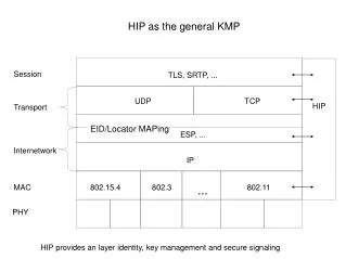
Overview of TGaf PHY Design: Enhanced Channel Support and Transmission Requirements
This document provides a high-level overview of the TGaf PHY design, primarily focusing on its specifications as outlined in clause 23. Key design requirements include high ACLR at -55 dB at channel edges for maximum power transmissions, support for various channel widths (6, 7, 8 MHz), and improvements over previous standards like 802.11ac. The PHY design accommodates both contiguous and non-contiguous channel transmissions, optimizing performance in urban areas with limited spectrum, and ensuring increased delay spread tolerance for outdoor applications.

Overview of TGaf PHY Design: Enhanced Channel Support and Transmission Requirements
E N D
Presentation Transcript
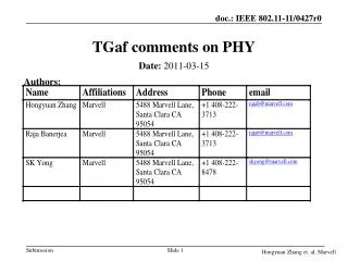
TGaf PHY Overview Authors: Date:2012-07-20 Ron Porat, Broadcom
Outline • Provide high level description of the PHY design for TGaf as described in clause 23 Ron Porat, Broadcom
Design Requirements • High ACLR – 55dB at the channel edge for transmissions at maximum allowed power • Much higher than current 802.11 where channel edge spectral mask value is at around -20dBr • Support for 3 basic channel widths – 6,7,8MHz • Support for contiguous and non-contiguous transmission of the basic channel unit (due to scarcity of spectrum in urban area) • Unlike 11ac where non-contiguous is supported only for the third largest BW • Re-use 11ac with modifications specific to TGaf • Support for longer delay spread outdoor deployments Ron Porat, Broadcom
PHY Details – One Channel • The PHY for one TVWS channel is based on the 11ac 40MHz PHY as-is with a sampling frequency clock change • Sampling clock change increases symbol length and delay spread tolerance to meet 11af requirements. The alternative of using 20MHz PHY was considered but it was decided that it doesn’t provide long enough delay spread for outdoor applications (increase by less than 3 for 8MHz channels is insufficient) • VHT and non-HT DUP modes are the only supported modes • Signal BW occupies about 81% (compared to 91% in 11ac) of the TVWS channels in 6MHz and 8MHz regulatory domains. • This enables larger guard bands to allow filter roll off to achieve -55dBr ACLR • In order to reduce PHY implementation options: • 7MHz regulatory domains re-use the 6MHz PHY • Same PHY design for 6MHz and 8MHz channels with only a sampling clock change Ron Porat, Broadcom
Cont. – Multiple Channels • TVWS channels are divided into an even number of tones. This enables transmission and reception of multiple contiguous channels using one IFFT/FFT as in 11ac. 144 tones were chosen to meet the desired signal BW. • The PHY for multiple channels is based on the PHY for one channel. • This concept is similar to the 11ac design of 160MHz and 80+80MHz whereby the tone location of DATA and pilots are the same as in 80MHz. • All basic channel units (termed frequency segments in clause 23) are connected via a single encoder and interleaver in order to maximized frequency diversity gain (11af channels are much narrower than 11ac, 11af can be used in lower delay spread environments such as indoors where diversity in one channel is limited) Ron Porat, Broadcom
Clause 23 Structure • Clause 23 describes the PHY for TGaf. The methodology used in creating clause 23 is by copying all the section titles of 11ac (clause 22) and filling them only with differential information explaining the delta relative to clause 22 when applicable • Example: clause 23.3.8.1.2 L-STF definition using five lines to modify 20+ lines including a lot of math: The L-STF field for each frequency segment in any transmission mode is defined by Equation (20-9) in 20.3.9.3.3 (L-STF definition). The time domain representation of the signal on frequency iSeg segment in transmit chain iTX is specified in Equation (22-16) and where gk,BW is replaced by gk,M as defined in Table 23-7 (Transmission mode and) with NSR as defined in Table 23-3 (Timing-related parameters). Ron Porat, Broadcom
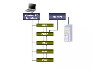
Example: Multi-Channel Transmitter • Due to the structure of the of the PHY, the same design holds for contiguous and non-contiguous channels Ron Porat, Broadcom
Example: Contiguous Multi-Channel Transmitter • Due to the fact that each channel consists of an integer and even number of tones some implementation can use one IFFT (or FFT at the receiver) Ron Porat, Broadcom