Download
1 / 40
400 likes | 600 Vues
Zach Michel, Jonathan Scislow Jamie Ottmar, Wenxiao Zeng. Hybrid Formula Car SD1115. Problem: Crude Oil Dependency. The United States is responsible for 25% of the world’s oil consumption Major contributor to pollution 1000 barrels of crude oil extracted every second. Solution:

E N D
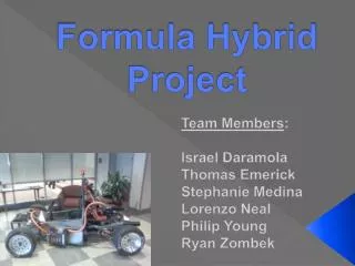
Zach Michel, Jonathan ScislowJamie Ottmar, WenxiaoZeng Hybrid Formula CarSD1115
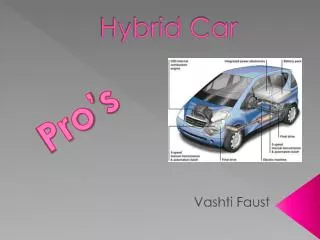
Problem: Crude Oil Dependency • The United States is responsible for 25% of the world’s oil consumption • Major contributor to pollution • 1000 barrels of crude oil extracted every second. Solution: Hybrid Electric Vehicles • Electric Vehicles are a greener alternative. • Allow for less pollution while still having an internal combustion engine for power. Info from: http://www.oildependency.org/
Requirements • Come up with an electrical drive system that would work together with an internal combustion engine to power a formula car. • Follow all safety restrictions and standards to ensure a completely safe system. • Adhere to the technical guidelines set forth by the Formula Hybrid™ Competition Committee • Keep the idea of a limited budget in mind while designing system.
Drive Train Configuration • Combustion engine and electric motor power the wheels • Engine is connected directly to wheels, eliminating inefficient energy conversion • Allows for the option of using regenerative braking • Advantages: • Requires smaller battery capacity • Eliminates inefficient energy loss • Works well in a highway condition • Disadvantages • Inefficient in stop-and-go situations. Parallel
3-Phase AC Induction Motor • Power is supplied to rotor by electromagnetic induction. • Speed is easily controlled • Relatively simple motor setup • High power availability • Smooth power and control • Generally have the lowest cost among electric motors
AC-15 Electric Motor • Manufactured by HPEVS (High Performance Electric Vehicle Systems) • Purchased from Thunderstruck Motors
Curtis 1238R Motor Controller • Tennant offered to donate a motor controller. • This controller was chosen based on its ability to handle high current requirements of our system • Uses VCL language (Vehicle Control Language) • Curtis 1311 Handheld programmer is used for programming and adjusting parameters. This was also donated by Tennant.
Curtis 1238R (cont.) • This controller is able to operate in torque control mode. • Works very well in a parallel hybrid configuration. • Designed for 72-96V systems. • 550A two-minute RMS current rating. • Meets IP65 environmental sealing standard.
Curtis 1238R (cont.) • Uses a 36 pin AMPSEAL connector. • We were given an unwired connector and wired up the harness using only the pins that our system needed.
Batteries • Decided to use Lithium-ion battery chemistry • Handle high current safely • High energy density • Ideal for powering electric motors • Rechargeable prismatic cells • Much more safe and reliable than many other chemistry options.
Batteries (cont.) • Purchased batteries from Flux Power • 3.2V 40AH Cells • Able to handle current that is required by the AC-15 electric motor, including the 300A momentary discharge • Current • 400A Impulse (2 secs) • 200A Peak (10 secs) • 120A Continuous • Voltage • 3.9V Max • 3.2V Nominal • 2.5V Minimum
Batteries (cont.) • Energy of our system (76.8V)(40 Ah)(0.8)(3600) = 8.85 MJ • Competition energy restriction = 19.5 MJ 8.85 MJ/19.5 MJ = 45.5% Electric • Our system’s continuous current will be around 60 A. (40Ah) / (60A) = 40 minutes
Battery Charger • Delta-Q QuiQ Charger • Purchased from Flux Power • Universal AC Input (85-265V) • 72V DC output, 100V Max • 12A charging current • Can be used with wide variety of battery chemistries • Fully sealed enclosure that can be stored onboard. • Safe and reliable.
Battery Management System • eLithionLithiumate Lite Li-Ion BMS • Designed specifically for EV conversions • Cell boards mounted on cells with a single wire connecting to adjacent cells • Can support up to 160 cells (~500V) in up to 8 banks. • Protects cells from over/under current and over/under voltage and temperature • Supports all form factors and chemistries. • Compatible with most chargers and motor controllers
Battery Management System (cont.) • Evaluation • Calculates and reports the state of charge of the battery pack • Management • Balances the voltage for each cell • Protection • Turns off charger if the any cell voltage exceeds maximum or charging current is excessive • Reduces motor drive power if battery is nearly empty • Requests that motor controller turn off if cell voltage drops below a minimum, or the discharging current is excessive • Disables charging if temperature is out of range, or if a cell board stops reporting its current state. • Prevents the user from driving away with the AC power plugged in.
Battery Management System (cont.) • Graphical User Interface • Connects a laptop via USB to the BMS. • Able to view and test any faults that are occurring. • Monitor individual cell voltages, current, temperature, etc in real time. • Must use GUI to set up battery chemistry and size of pack before BMS will function properly.
Ignition Switch • Located on the right side of the drivers seat. • When switch is up, system is powered.
Battery Management System • Switching ignition will give power to BMS. • LED’s on BMS will light up and display whether batteries are properly set up or if there are faults occurring • BMS master controller is located in the battery bank to the left of the vehicle operator.
Motor Controller • If there are no BMS faults, batteries will provide the necessary voltage to the motor controller • Motor controller status LEDs • Yellow blinking light means controller has no faults • Combination of Red/Yellow lights indicates that there are controller faults that need to be addressed.
Electric Motor • If there are no motor controller faults, electric motor is ready to spin. • Power is provided from motor controller to electric drive through 3 phase cables (U,V,W) • Wire is enclosed in orange conduit for safety reasons
Throttle Assembly • Two-wire potentiometer is wired behind the vehicle’s gas pedal. Connected to motor controller through the AMPSEAL connector • When pedal is suppressed, potentiometer will vary from ~0.5 V (resting point) to ~4 V (full throttle).
Low Voltage Controls • Motor controller has connections for throttle potentiometer, ignition, BMS, programmer, motor encoder, etc. • All of these connections are made through the AMPSEAL connector and provide the motor controller with the information necessary to properly operate the electric motor
System Safety • BMS can automatically disable the high voltage lines using a main contactor switch. • If the switch receives a signal from the BMS, the internal coil will charge and the contactor will open, shutting down the HV system.
System Safety (cont.) • The user can also disable the high voltage system manually. • 3 bright red emergency stops are on the vehicle • One on the right side of the steering wheel for use by the driver • One on either side behind the drivers head. These are for someone outside of the vehicle to use in case of emergency.
Fusing • Maximum current will be 300A • For this reason, a 400A fuse is used as protection for the HV system on the vehicle. • It is located at the positive end of the battery pack • Smaller additional fuses are located on the AC power to the charger (15A) as well as the connection between the BMS and battery pack (20A, used for charging). • Additionally, the AC power to the charger runs through a AC relay controlled by the BMS. • A low power fuse (1A) between the AC line and the BMS. • A 10A fuse is also in line with the ignition switch
Problems Encountered • Main problem was gaining access to batteries. • Not allowed to use batteries until qualified. • Took several training courses and ordered safety equipment. • Finally given access after 1 month • Put us way behind schedule and gave us only a few days to assemble and test our system.
Problems Encountered • Inadequate budget also a main concern • Parts for our system were very expensive and the ECE budget was low. • Forced to rely on SAE and Mechanical Engineering funds. • We had many delays purchasing parts because of issues with transferring funds and ordering parts through the ME dept.
Lessons Learned • Working on an inter-group project can be extremely difficult • Our communication skills were greatly improved • We learned how to effectively communicate with other engineering students, businesses, and within our own group • This project was unique in that it was more like a real world project where you have to work efficiently with other departments and companies
Lessons Learned • We learned a great amount about power electronics, safety, and mechanical engineering design considerations. • A lot of research was done in order to make sure that we met all design requirements. • We didn’t have much support on this so it was a lot of learning on our own. • Companies are rarely helpful unless you place large and expensive orders so we were usually on our own to figure everything out by ourselves.
Future Work • Characterizing electric motor • Motor should be rigorously tested to achieve peak performance and proper current distribution over the 3 phases. • Additional testing and tweaking of programmer settings. • Investigate and implement regenerative braking techniques • Could potentially improve battery life and improve endurance competition results. • Further review of safety rules and regulations • Could potentially wire interlock to gas pedal.
Summary • We developed a fully functional electrical system for a hybrid vehicle • We came up with the overall design and connected the entire electrical system • The electrical system including the electric motor is up and running • Given our time and budget constraints we see this as a huge accomplishment • Our User’s Manual and Technical Description should guide the Mechanical Engineering team to finish whatever we didn’t have time to implement • The motor has yet to be tuned and optimized, but we researched how to program it and did as much as we could with our time constraints • We determined what work has yet to be done (mainly tuning the motor and a few changes to meet competition standards) and are communicating this to the Mechanical Engineering design team • All design work has been completed. What remains is simply implementing the things we were only able to research
Summary • Through the course of Design 2 and 3 we went from knowing nothing about vehicles or motors to building a working electrical system for a hybrid vehicle • We learned how to improvise and re-evaluate design considerations in an efficient and time effective manner • We were on a serious time crunch and things didn’t often go as expected, but we were able to work past all problems encountered • A follow on design team or interest group would be possible, but a design team would likely have to work on multiple projects