Download
1 / 27
280 likes | 790 Vues
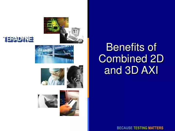
Benefits of Combined 2D and 3D AXI. Agenda. Inspection Technology Challenges 2D Transmissive AXI Inspection 3D AXI (ClearVue ™ ) Inspection Combined 2D and 3D AXI Inspection. AOI - No visual access to the BGA connections

E N D
Agenda • Inspection Technology Challenges • 2D Transmissive AXI Inspection • 3D AXI (ClearVue™) Inspection • Combined 2D and 3D AXI Inspection
AOI - No visual access to the BGA connections ICT - No access to parallel capacitors, multiple VCC and GND pins on BGAs ICT – Possible loss of electrical net access due to component density Inspection Technology Challenges – Best example BGA • Transmissive 2D AXI – can test the BGA but will see components on the opposite sides of the board potentially limiting defect coverage • 3D AXI - allows for inspection of double sided boards by using “slicing” technology
Detector PCB X-RAYS Transmissive X-Ray Source High-Speed 2D Transmissive AXI
High-Speed 2D Transmissive AXI • Provides: • Large FOV high resolution imaging • Uses a large detector (Xstation MX = 4.4 in²) • Fast automated X-ray technique • With a large FOV and typically only one image acquire required • Full 3D solder joint images • Images contain all the solder joint information • High image quality • No image degradation by 3D image reconstruction • Full FOV analysis available • 3D only looks at regions of interest in a slice
High Resolution Transmissive Images High-Speed 2D Transmissive AXI – Large FOV • High Resolution Transmissive Images • 4096 bits of gray scale – minimize image acquire times Actual Resolution
High-Speed 2D Transmissive AXI – High Throughput When components are not obscured this technique allows for the fastest inspection to take place. XStation MX throughput is 6 in²/sec (30 cm²/sec).
High-Speed 2D Transmissive AXI – Retains Full Joint Information • Algorithms extract solder joint features from 4,096-bit grey scale to determine: • Width (Sub-Pixel Accuracy) • Heel Solder • Toe Solder • Pad Solder • Fillet Shape / Slope • Side Fillet Shape • Length • Plus GULLWING SOLDER JOINT X-Ray Image Heel Fillet Side Fillets Toe Fillet Heel Fillet Toe Fillet Side Fillet Transmission 3D Solder Joint Profile
High-Speed 2D Transmissive AXI – High Image Quality 3D image reconstruction loses image quality – Some are worse than others! Laminography X-Ray Transmissive AXI Better image quality and lower noise reduces false fails and increases fault detection. Both images have been enlarged for this example, and have the same pad width and length.
High-Speed 2D Transmissive AXI – High Image Quality • As an example of image quality and how that translates to defect detection. Here is an example of Void Measurements • Laminographic 3D AXI solutions lose detection below 10mils. On a 35mil ball this can equate to any void less than 20% not detected. Transmissive AXI Laminography AXI * % of voiding on 35 mil PBGA Balls, 1” FOV.
High-Speed 2D Transmissive AXI – High Fault Coverage • Slicing on warped boards can leave areas of the board un-inspected • Areas outside the region of interest in the FOV of the slice are not inspected • Shorts or solder balls can be in areas that can never be detected with a pure 3D system Slice Slice
High-Speed 2D Transmissive AXI • Limitations: • Hidden or obscured solder Joints • Limitations: • Hidden or obscured solder Joints • Certain joint types • CCGA • QFN • Non-eutectic BGA’s • Etc.
High-Speed 2D Transmissive AXI – Summary • Transmissive 2D AXI Advantages • All components inspected at beat rate of the line • Out of slice detection for shorts, solder balls, etc. • Complete range of voids evaluation on eutectic solder joints • Inspection of small geometry components • Full volumetric measurement of solder joints
4.4” A B A Range used 23o - 41o 2.2” 3D (ClearVue™) Image Reconstruction Detector PCB Transmission X-Ray Source The detector area is divided into 9 regions, each region is 1/9 of a particular FOV
X T T B B Z B T T B T B B B B T T T 3D ClearVueSlicing Capabilities
Top Slice Pad Slice T T T T T T B B B B B B Bottom Slice B B B T T T T T T B B B T T T B B B B B B B B B B B B T T T T T T T T T 3D ClearVue Provides Clear, Accurate Slices T B B T Objects at different elevations move by different horizontal distances allowing for automated Z height detection “Max Value” algorithm removes artifacts
Example:- Connection blades of a NeXLev connector obscure joints 3D ClearVue Provides Clear, Accurate Slices ClearVue removes obscurations that limit 2D defect detection
Off-axis X-Rays Non-eutectic ball Eutectic solder fillet Voids Pad 3D ClearVue Angled Image Defect Detection • Some solder joints require an angle so they can be inspected • Other joints require an angle just to be viewed Ceramic Column Grid Array
3D ClearVue Image Reconstruction - Summary • 3D X-Ray Advantage • Inspection of hidden or obscured solder joints • Clear 3D slices of obscured joints that enable accurate defect detection • Eg NeXLex connectors • Full inspection of joint types that require angled views • Non-eutectic solder balls • Ceramic column grid arrays • QFNs
Teradyne’s Combined 2D and 3D AXI ApproachXStation MX combines the techniques needed to ensure the most efficient and effective inspection solution
Transmissive 2D AXI vs. 3D AXI Comparisons Good Medium Poor
Typical 2D AXI vs. 3D AXI Coverage • Even dense boards have a high percentage of non-obscured solder joints • In these examples, 80-98% of the boards were inspected with high- speed 2D AXI • Only 2 boards required more than 10% 3D AXI inspection
High Throughput Requirements – Use High Speed 2D AXI • To perform 100% inspection, the AXI cell (Inspection and verification) must keep up with the beat rate of the line • 2D AXI operates at 6.0 in²/sec (30 cm²/sec) • 3D AXI is dependant on the joint type, but the XStation MX typically operates at 0.64 in²/sec • Some boards only require high-speed 2D AXI for 100% inspection
Transmissive 2D AXI All components inspected at beat rate of the line Out of slice detection for shorts, solder balls etc. Complete range of voids evaluation on eutectic solder joints Inspection of small geometry components Full volumetric measurement of solder joints 3D X-Ray Inspecting of hidden/obscurations solder joints Clear 3D Slices that enable defect detection eg. NeXLex Connectors Full inspection of joint types that require angled views eg. Non-eutectic solder balls Ceramic column grid arrays QFNs Unique Defect Coverage for Each AXI Technology

![Formula’s and Properties Of 2D and 3D Shapes.! :]](https://cdn3.slideserve.com/6593022/formula-s-and-properties-of-2d-and-3d-shapes-dt.jpg)