Download
1 / 37
370 likes | 372 Vues
The Global Design Effort (GDE) is responsible for producing a comprehensive design for the International Linear Collider (ILC), including detailed concepts, performance assessments, costing, and industrialization plans. This article discusses the progress and key decisions made by the GDE in designing the ILC.

E N D
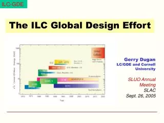
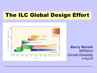
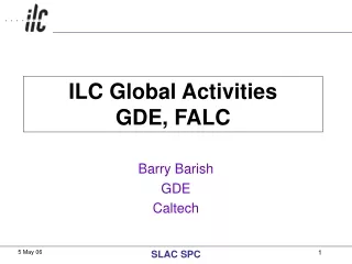
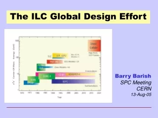
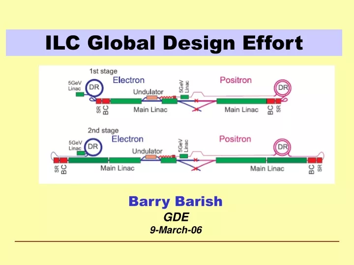
ILC Global Design Effort Barry Barish GDE 9-March-06
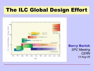
Global Design Effort (GDE) • On March 18, 2005, during the opening of LCWS05 workshop at Stanford University, I officially accepted the position of Director of the (yet to be formed) GDE LCWS06 Bangalore
Global Design Effort • The Mission of the GDE • Produce a design for the ILC that includes a detailed design concept, performance assessments, reliable international costing, an industrialization plan , siting analysis, as well as detector concepts and scope. • Coordinate worldwide prioritized proposal driven R & D efforts (to demonstrate and improve the performance, reduce the costs, attain the required reliability, etc.) LCWS06 Bangalore
GDE Begins at Snowmass GDE Members Americas 22 Europe 24 Asia 16 LCWS06 Bangalore
Barish - Snowmass Plenary Talk LCWS06 Bangalore
Designing a Linear Collider Superconducting RF Main Linac LCWS06 Bangalore
Baseline Configuration Document • Our ‘Deliverable’ by the end of 2005 • A structured electronic document • Documentation (reports, drawings etc) • Technical specs. • Parameter tables LCWS06 Bangalore
Structure of the BCD Summary-like overview for those who want to understand the choice and the why Technical documentation of the baseline, for engineers and acc. phys. making studies towards RDR LCWS06 Bangalore
Alternatives Section(s) NoteACD is part of the BCD LCWS06 Bangalore
The Key Decisions Critical choices: luminosity parameters & gradient LCWS06 Bangalore
Making Choices – The Tradeoffs Many decisions are interrelated and require input from several WG/GG groups LCWS06 Bangalore
Parametric Approach • A working space - optimize machine for cost/performance LCWS06 Bangalore
From Snowmass to a Baseline 2005 Snowmass August September October November December WW/GG summaries Response to list of 40+ decisions All documented ‘recommendations available on ILC Website (request community feedback) Review by BCD EC BCD EC publishes‘strawman’ BCD BCD Executive Committee: BarishDugan, Foster, Takasaki Raubenheimer, Yokoya, Walker Public Review Frascati GDE meeting LCWS06 Bangalore
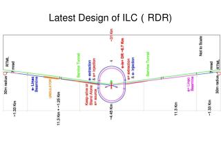
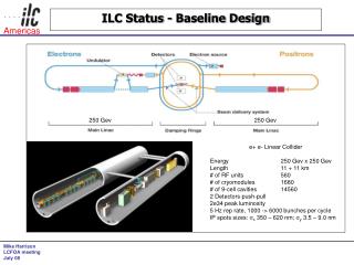
The Baseline Machine (500GeV) ~30 km ML ~10km (G = 31.5MV/m) 20mr RTML ~1.6km 2mr BDS 5km e+ undulator @ 150 GeV (~1.2km) x2 R = 955m E = 5 GeV not to scale LCWS06 Bangalore
Positron-style room-temperature accelerating section E=70-100 MeV laser standard ILC SCRF modules diagnostics section sub-harmonic bunchers + solenoids Electron Source • DC Guns incorporating photocathode illuminated by a Ti: Sapphire drive laser. • Long electron microbunches (~2 ns) are bunched in a bunching section • Accelerated in a room temperature linac to about 100 MeV and SRF linac to 5 GeV. LCWS06 Bangalore
Primary e- source Beam Delivery System IP 250 GeV e- DR Positron Linac 150 GeV 100 GeV Helical Undulator In By-Pass Line Photon Collimators e+ DR Target e- Dump Photon Beam Dump Photon Target Adiabatic Matching Device e+ pre-accelerator ~5GeV Auxiliary e- Source Positron Source • Helical Undulator Based Positron Source with Keep Alive System Keep Alive: This source would have all bunches filled to 10% of nominal intensity. LCWS06 Bangalore
ILC Small Damping Ring Multi-Bunch Trains with inter-train gaps LCWS06 Bangalore
ILC Damping Ring: Baseline Design • Positrons: • Two rings of ~6 km circumference in a single tunnel. • Two rings are needed to reduce e- cloud effects unless significant progress can be made with mitigation techniques. • Preferred to 17 km dogbone due to: • Space-charge effects • Acceptance • Tunnel layout (commissioning time, stray fields) • Electrons: • One 6 km ring. LCWS06 Bangalore
Main Linac: SRF Cavity Gradient Total length of one 500 GeV linac 20km * assuming 75% fill factor LCWS06 Bangalore
Cavity: R&D • Material R&D: Fine, Large, Single Crystal • Fabrication • A number of minor modifications and improvements could be implemented without impact to the basic cavity design. • Cavity Preparation • Buffer Chemical Processing • Cavity Processing (strong R&D needed) • Electro-polishing (EP) System • High Pressure Rinsing (HPR) • Assembly Procedure LCWS06 Bangalore
Superconducting RF Cavities High Gradient Accelerator 35 MV/meter -- 40 km linear collider LCWS06 Bangalore
Improved ProcessingElectropolishing Chemical Polish Electro Polish LCWS06 Bangalore
RF Power: Modulator Baseline Alternate Operation: an array of capacitors is charged in parallel, discharged in series. (~2m)Will test full prototype in 2006 The Bouncer Compensated Pulse Transformer Style Modulator LCWS06 Bangalore
RF Power: Baseline Klystrons Specification: 10MW MBK 1.5ms pulse 65% efficiency Thales CPI Toshiba LCWS06 Bangalore
Increase diameter beyond X-FEL Increase diameter beyond X-FEL Review 2-phase pipe size and effect of slope ILC Cryomodule LCWS06 Bangalore
ILC Beam Delivery System • Baseline • two BDSs, 20/2mrad, 2 detectors, 2 longitudinally separated IR halls • Alternative 1 • two BDSs, 20/2mrad, 2 detectors in single IR hall @ Z=0 • Alternative 2 • single IR/BDS, collider hall long enough for two push-pull detectors LCWS06 Bangalore
ILC Siting and Conventional Facilities • The design is intimately tied to the features of the site • 1 tunnels or 2 tunnels? • Deep or shallow? • Laser straight linac or follow earth’s curvature in segments? • GDE ILC Design will be done to samples sites in the three regions LCWS06 Bangalore
The GDE after Six Months • How have we done? • We are on track – BCD produced by end of 2005 as promised. It will provide a sound basis for entering into a reference design effort, globally coordinate R&D program, begin industrialization, determine costs, etc. next year • What’s Next? • Undertaking Design/Cost effort toward Reference Design Report (RDR) • Assessing present R&D program to begin to provide global guidance in the future. LCWS06 Bangalore
Next Goal – Reference Design • Reorganized the GDE toward Design / Cost Effort • A global effort to design / cost the ILC is underway and working • Configuration Control; International Costing; Industrialization; Siting -------------------------- • A sound design must be established with convincing and affordable costing. • Global R&D program to demonstrate the ILC, improve over the baseline and reduce costs. LCWS06 Bangalore
GDE RDR / R&D Organization FALC ICFA FALC Resource Board ILCSC GDE Directorate GDE Executive Committee GDE R & D Board GDE Change Control Board GDE Design Cost Board Global R&D Program RDR Design Matrix LCWS06 Bangalore
GDE RDR / R&D Organization FALC ICFA Reporting FALC Resource Board ILCSC technical resources GDE Directorate GDE Executive Committee GDE R & D Board GDE Change Control Board GDE Design Cost Board Global R&D Program RDR Design Matrix LCWS06 Bangalore
GDE RDR / R&D Organization FALC ICFA FALC Resource Board ILCSC GDE Directorate GDE GDE Executive Committee GDE R & D Board GDE Change Control Board GDE Design Cost Board Global R&D Program RDR Design Matrix LCWS06 Bangalore
GDE RDR / R&D Organization FALC ICFA FALC Resource Board ILCSC GDE Directorate GDE Executive Committee GDE R & D Board GDE Change Control Board GDE Design Cost Board Global R&D Program RDR Design Matrix ILC Design Effort ILC R&D Program LCWS06 Bangalore
Cost Roll-ups e- e+ damping RTML main BDS source source rings linac Area Systems LCWS06 Bangalore
2006 From Baseline to a RDR July Dec Jan Frascati Bangalore Vancouver Valencia Freeze Configuration Organize for RDR Review Design/Cost Methodology Review Initial Design / Cost Review Final Design / Cost RDR Document Design and Costing Preliminary RDR Released LCWS06 Bangalore
2005 2006 2007 2008 2009 2010 Global Design Effort Project Baseline configuration Reference Design Internationl Linear Collider Timeline Technical Design ILC R&D Program Expression of Interest to Host International Mgmt
Conclusions • The baseline configuration for the ILC has been established and is document in the BCD (a 700+ page electronic document) • We have put the BCD under configuration control and are evolving it now in a controlled manner • The BCD also defines alternatives and the combination of the baseline and alternative will give good guidance for the ILC R&D program • The BCD is now being used as the reference and basis for the reference design / cost effort this year. This is a much tougher job! LCWS06 Bangalore