Download
1 / 33
360 likes | 383 Vues
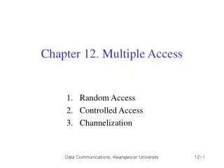
Chapter 12 Multiple Access. Figure 12.1 Data link layer divided into two functionality-oriented sublayers. Figure 12.2 Taxonomy of multiple-access protocols discussed in this chapter. 12-1 RANDOM ACCESS.

E N D
Chapter 12 Multiple Access
Figure 12.1 Data link layer divided into two functionality-oriented sublayers
Figure 12.2 Taxonomy of multiple-access protocols discussed in this chapter
12-1 RANDOM ACCESS In random access or contention methods, no station is superior to another station and none is assigned the control over another. No station permits, or does not permit, another station to send. At each instance, a station that has data to send uses a procedure defined by the protocol to make a decision on whether or not to send. Topics discussed in this section: ALOHACarrier Sense Multiple Access Carrier Sense Multiple Access with Collision Detection Carrier Sense Multiple Access with Collision Avoidance
Example 12.1 The stations on a wireless ALOHA network are a maximum of 600 km apart. If we assume that signals propagate at 3 × 10⁸ m/s, we find Tp = (600 × 105 ) / (3 × 10⁸ ) = 2 ms. Now we can find the value of TB for different values of K . a. For K = 1, the range is {0, 1}. The station needs to| generate a random number with a value of 0 or 1. This means that TB is either 0 ms (0 × 2) or 2 ms (1 × 2), based on the outcome of the random variable.
Example 12.1 (continued) b. For K = 2, the range is {0, 1, 2, 3}. This means that TBcan be 0, 2, 4, or 6 ms, based on the outcome of the random variable. c. For K = 3, the range is {0, 1, 2, 3, 4, 5, 6, 7}. This means that TB can be 0, 2, 4, . . . , 14 ms, based on the outcome of the random variable. d. We need to mention that if K > 10, it is normally set to 10.
Example 12.2 A pure ALOHA network transmits 200-bit frames on a shared channel of 200 kbps. What is the requirement to make this frame collision-free? Solution Average frame transmission time Tfr is 200 bits/200 kbps or 1 ms. The vulnerable time is 2 × 1 ms = 2 ms. This means no station should send later than 1 ms before this station starts transmission and no station should start sending during the one 1-ms period that this station is sending.
Note G the average number of frames generated by the system during one frame transmission time. Then it can be proved that the average number of successful transmissions for pure ALOHA is S = G x e-2G. The throughput for pure ALOHA is S = G × e −2G . The maximum throughput Smax = 0.184 when G= (1/2).
Example 12.3 A pure ALOHA network transmits 200-bit frames on a shared channel of 200 kbps. What is the throughput if the system (all stations together) produces a. 1000 frames per second b. 500 frames per second c. 250 frames per second. Solution The frame transmission time is 200/200 kbps or 1 ms. a. If the system creates 1000 frames per second, this is 1 frame per millisecond. The load is 1. In this case S = G× e−2 G or S = 0.135 (13.5 percent). This means that the throughput is 1000 × 0.135 = 135 frames. Only 135 frames out of 1000 will probably survive.
Example 12.3 (continued) b. If the system creates 500 frames per second, this is (1/2) frame per millisecond. The load is (1/2). In this case S = G × e −2G or S = 0.184 (18.4 percent). This means that the throughput is 500 × 0.184 = 92 and that only 92 frames out of 500 will probably survive. Note that this is the maximum throughput case, percentagewise. c. If the system creates 250 frames per second, this is (1/4) frame per millisecond. The load is (1/4). In this case S = G × e −2G or S = 0.152 (15.2 percent). This means that the throughput is 250 × 0.152 = 38. Only 38 frames out of 250 will probably survive.
Slotted ALOHA network • Pure ALOHA has a vulnerable time of 2 x Tfr . • No rule that defines when the station can send. • A station may send soon after another station has started or soon before another station has finished. • Slotted ALOHA was invented to improve the efficiency of pure ALOHA. • In slotted ALOHA we divide the time into slots of Tfr s and force the station to send only at the beginning of the time slot.
Note The throughput for slotted ALOHA is S = G × e−G . The maximum throughput Smax = 0.368 when G = 1.
Example 12.4 A slotted ALOHA network transmits 200-bit frames on a shared channel of 200 kbps. What is the throughput if the system (all stations together) produces a. 1000 frames per second b. 500 frames per second c. 250 frames per second. Solution The frame transmission time is 200/200 kbps or 1 ms. a. If the system creates 1000 frames per second, this is 1 frame per millisecond. The load is 1. In this case S = G× e−G or S = 0.368 (36.8 percent). This means that the throughput is 1000 × 0.0368 = 368 frames. Only 386 frames out of 1000 will probably survive.
Example 12.4 (continued) b. If the system creates 500 frames per second, this is (1/2) frame per millisecond. The load is (1/2). In this case S = G × e−G or S = 0.303 (30.3 percent). This means that the throughput is 500 × 0.0303 = 151. Only 151 frames out of 500 will probably survive. c. If the system creates 250 frames per second, this is (1/4) frame per millisecond. The load is (1/4). In this case S = G × e −G or S = 0.195 (19.5 percent). This means that the throughput is 250 × 0.195 = 49. Only 49 frames out of 250 will probably survive.
Figure 12.10 Behavior of three persistence methods 1-persistent method is simple and straightforward. In this method, after the station finds the line idle, it sends its frame immediately. This method has the highest chance of collision because two or more stations may find the line idle and send their frames immediately. In the non-persistent method, a station that has a frame to send senses the line. If the line is idle, it sends immediately. If the line is not idle, it waits a random amount of time and then senses the line again. The non-persistent approach reduces the chance of collision because it is unlikely that two or more stations will wait the same amount of time and retry to send simultaneously.
Example 12.5 A network using CSMA/CD has a bandwidth of 10 Mbps. If the maximum propagation time (including the delays in the devices and ignoring the time needed to send a jamming signal, as we see later) is 25.6 μs, what is the minimum size of the frame? Solution The frame transmission time is Tfr = 2 × Tp = 51.2 μs. This means, in the worst case, a station needs to transmit for a period of 51.2 μs to detect the collision. The minimum size of the frame is 10 Mbps × 51.2 μs = 512 bits or 64 bytes. This is actually the minimum size of the frame for Standard Ethernet.
Figure 12.15 Energy level during transmission, idleness, or collision
Note In CSMA/CA, the IFS can also be used to define the priority of a station or a frame.
Note In CSMA/CA, if the station finds the channel busy, it does not restart the timer of the contention window; it stops the timer and restarts it when the channel becomes idle.